One Week Course:
Build a Small Wind Turbine with Kostas Latoufis
August 21 to 27 2017, Montemor-o-Novo, Alentejo, Portugal

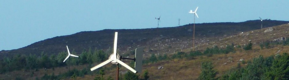
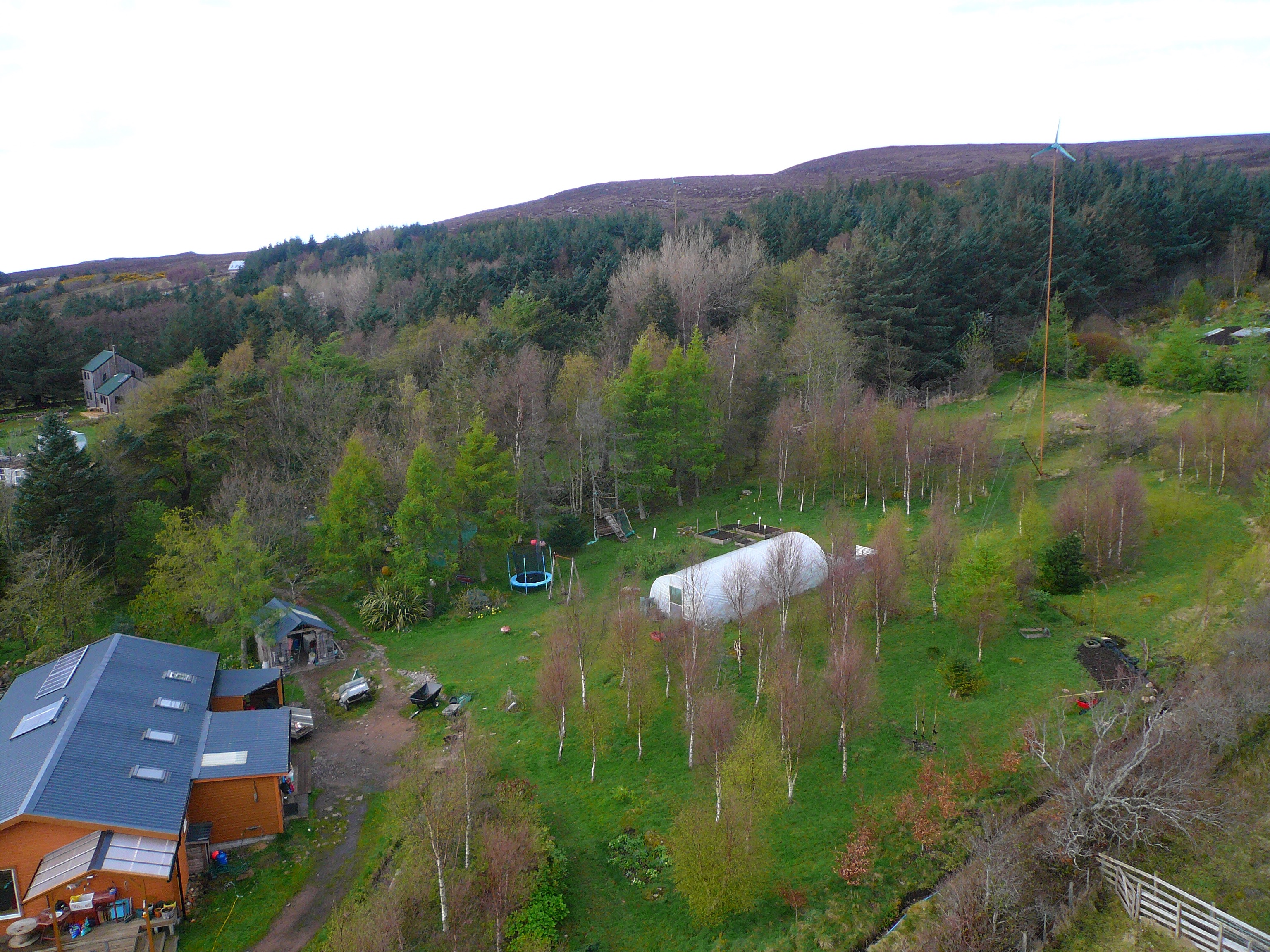
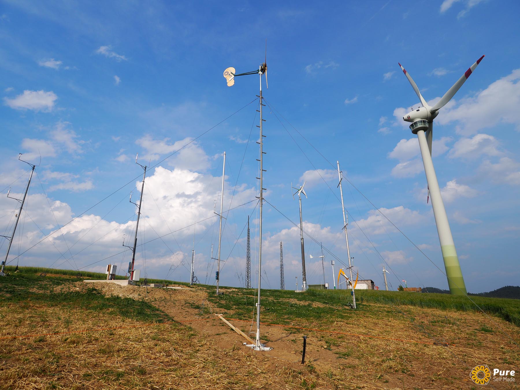
The wind turbines built in the workshops are based on the designs of Hugh Piggott, a renewable energy expert living in the off-grid community of Scoraig (Scotland), as described in his ‘Wind Turbine Recipe Book’. These wind turbines can be constructed with the use of common materials, simple manufacturing techniques and basic tools, providing a low cost small wind turbine that anyone can built. Hundreds of homemade small wind turbines have been constructed worldwide using these designs, and have proven to be robust, efficient, easy to maintain and quick to repair. Typical applications of locally manufactured small wind turbines are development projects such as electrification of village communities in the global south, educational projects in universities and schools and sustainability projects such as renewable energy electrification of ecovillages. ‘Nea Guinea’ has been organizing small wind turbine construction workshops since 2009 and has empowered many people with the knowledge of harnessing power from the wind.
Course Program
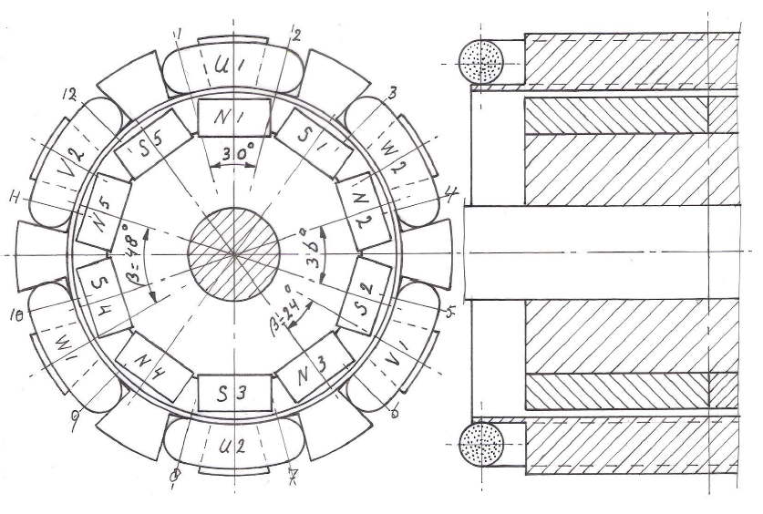
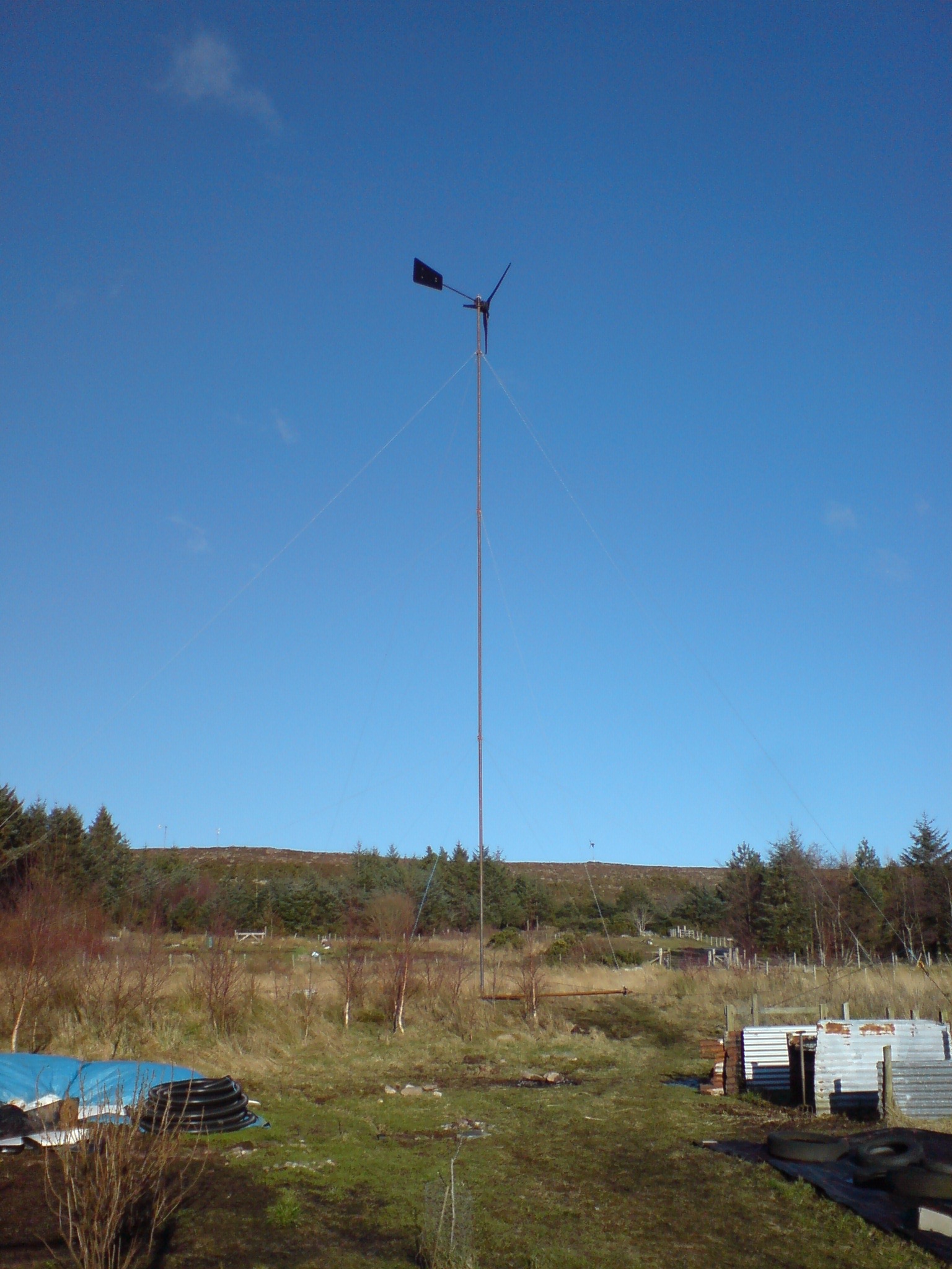
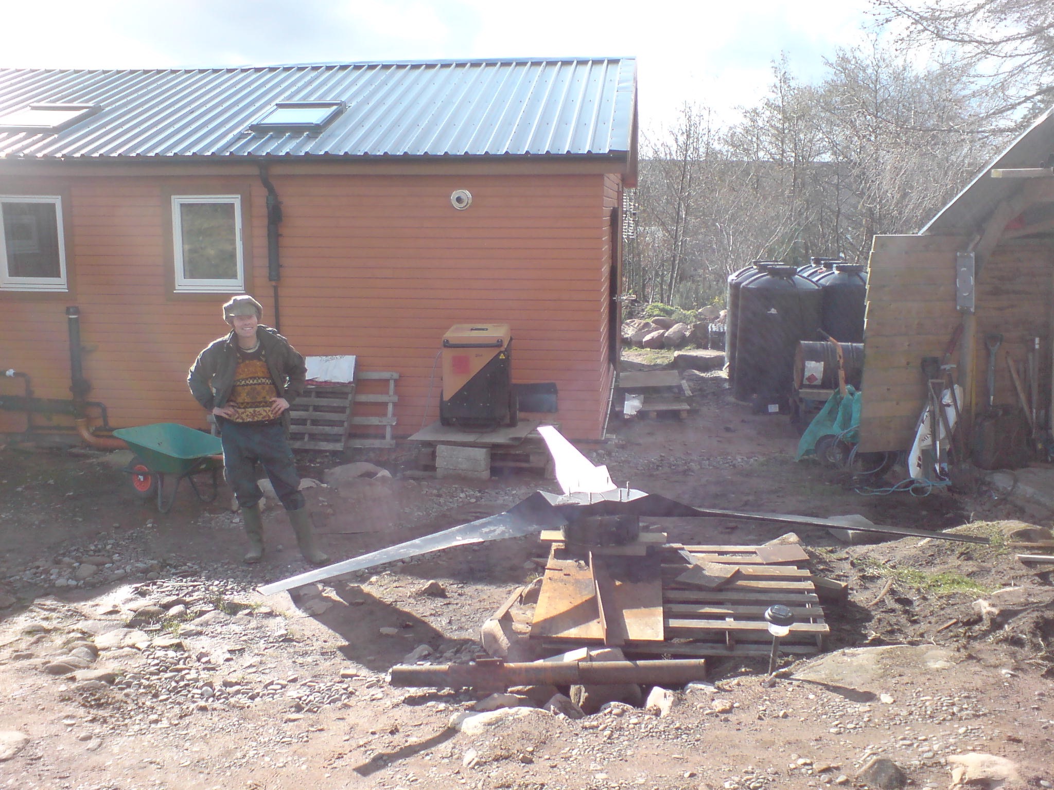
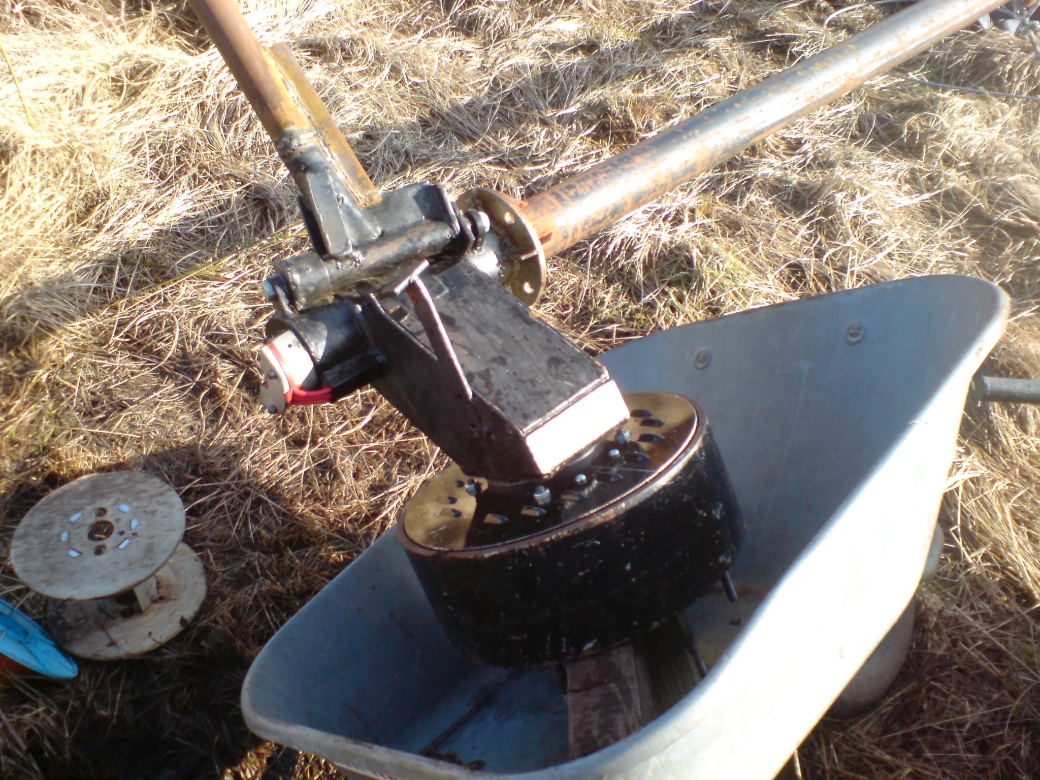
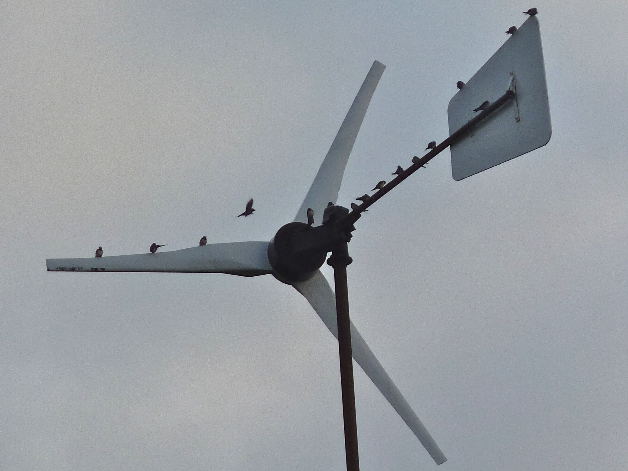
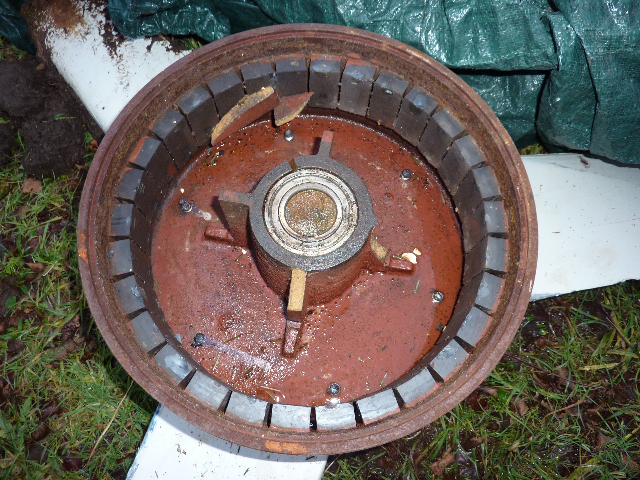
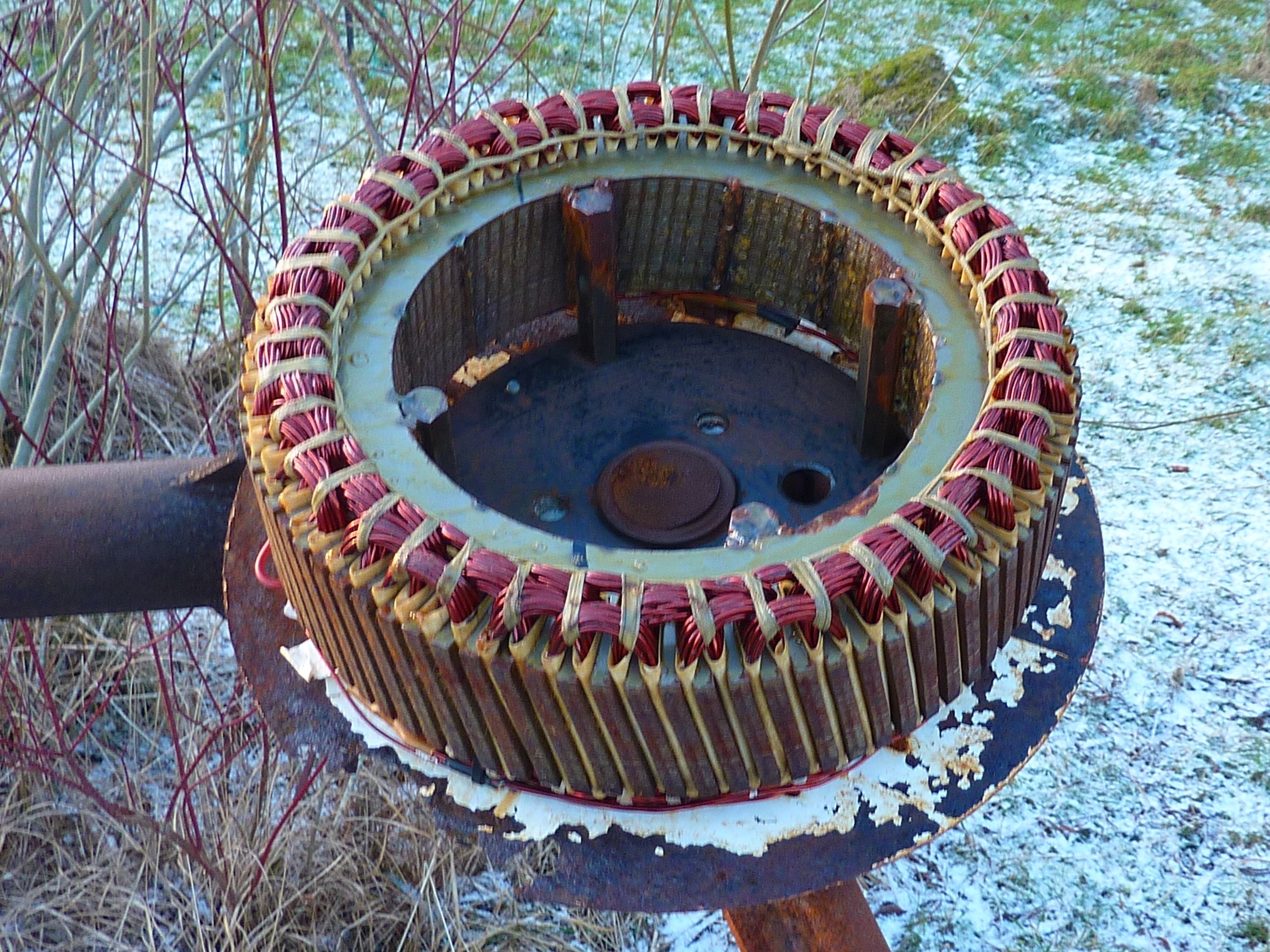
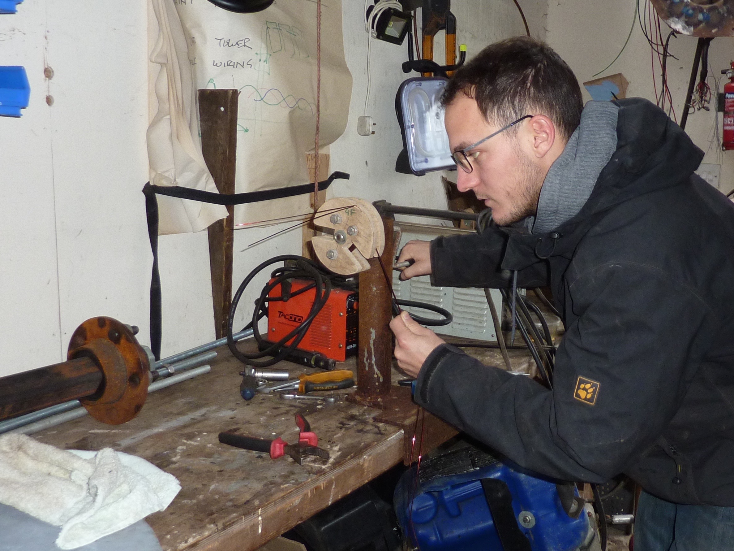
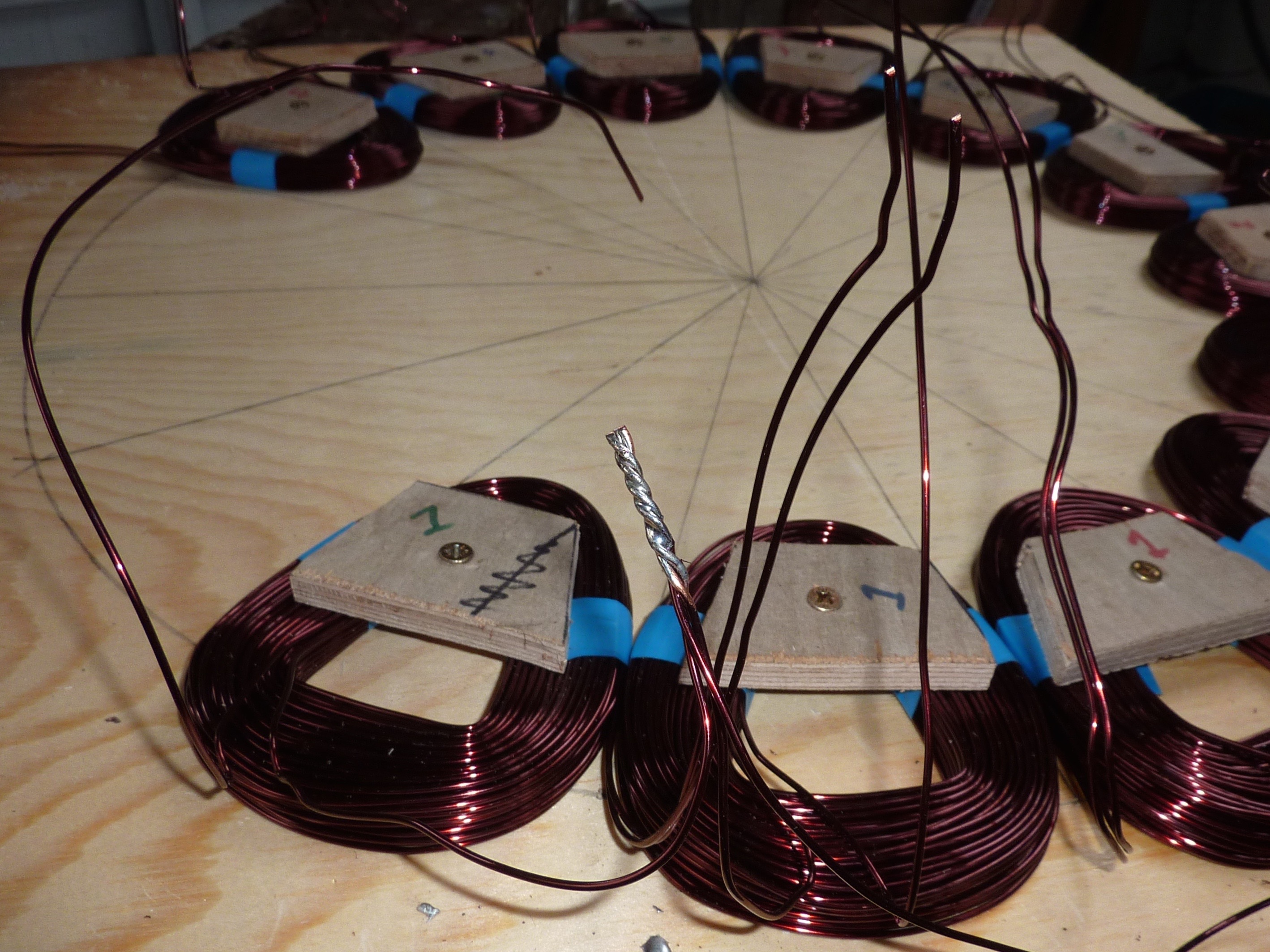
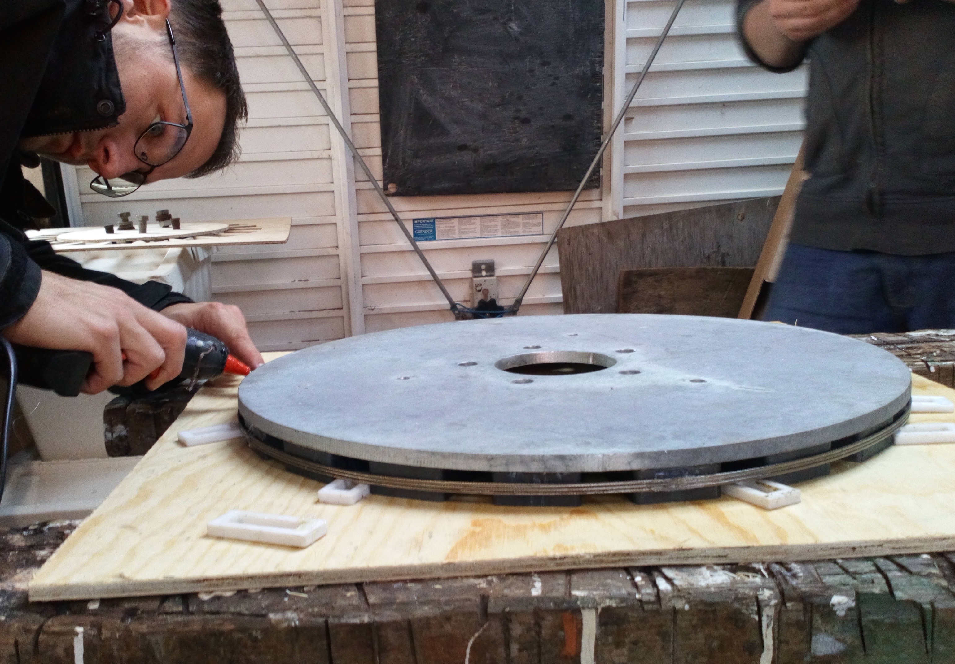
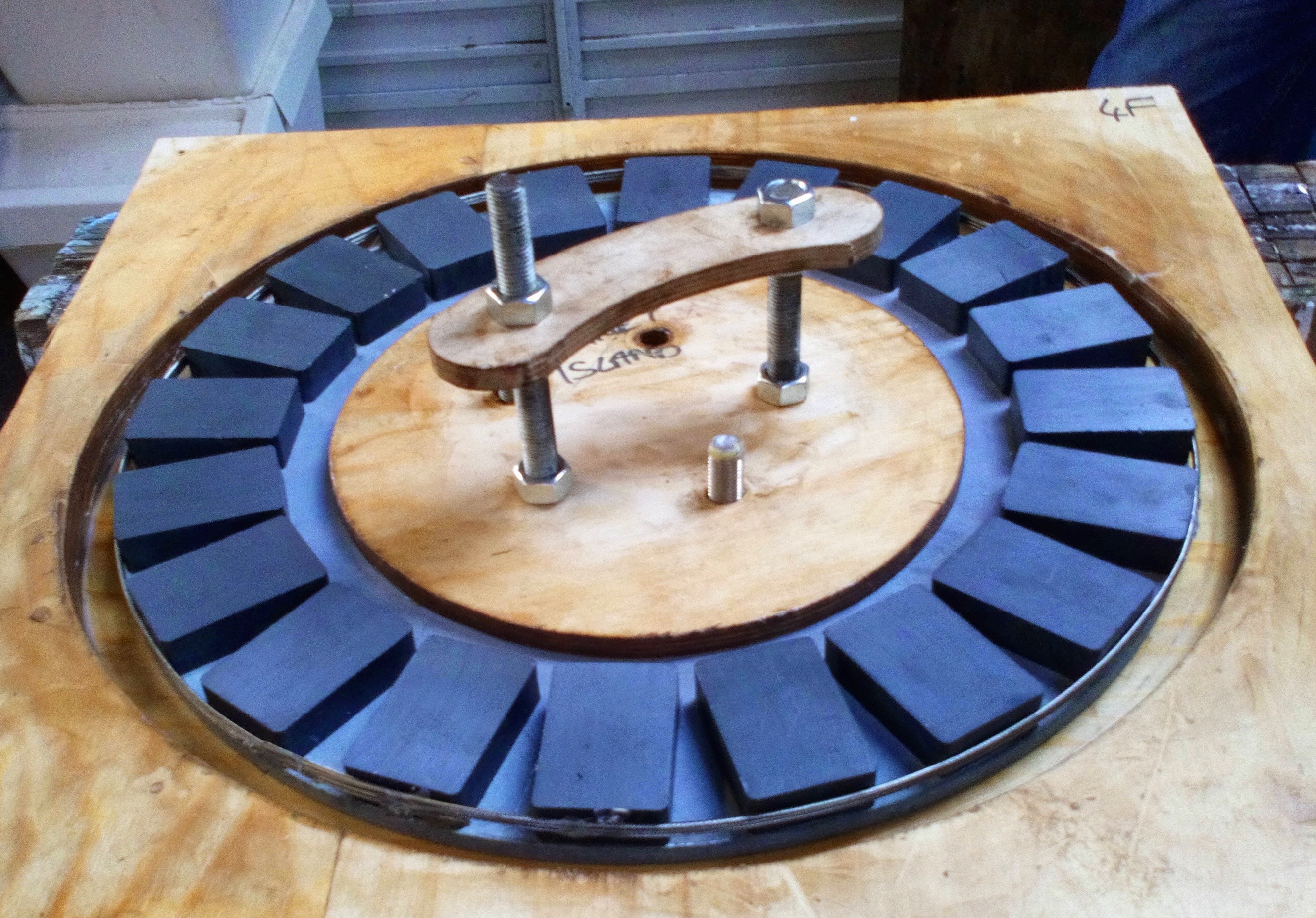
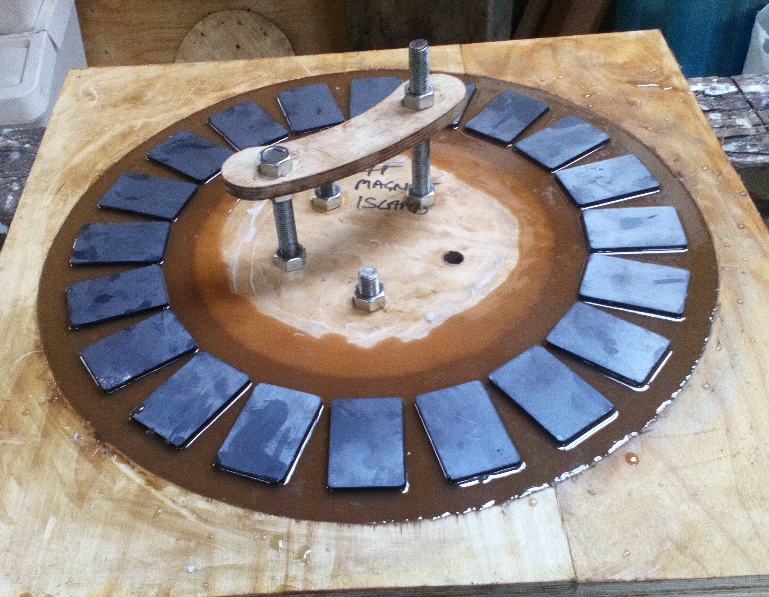
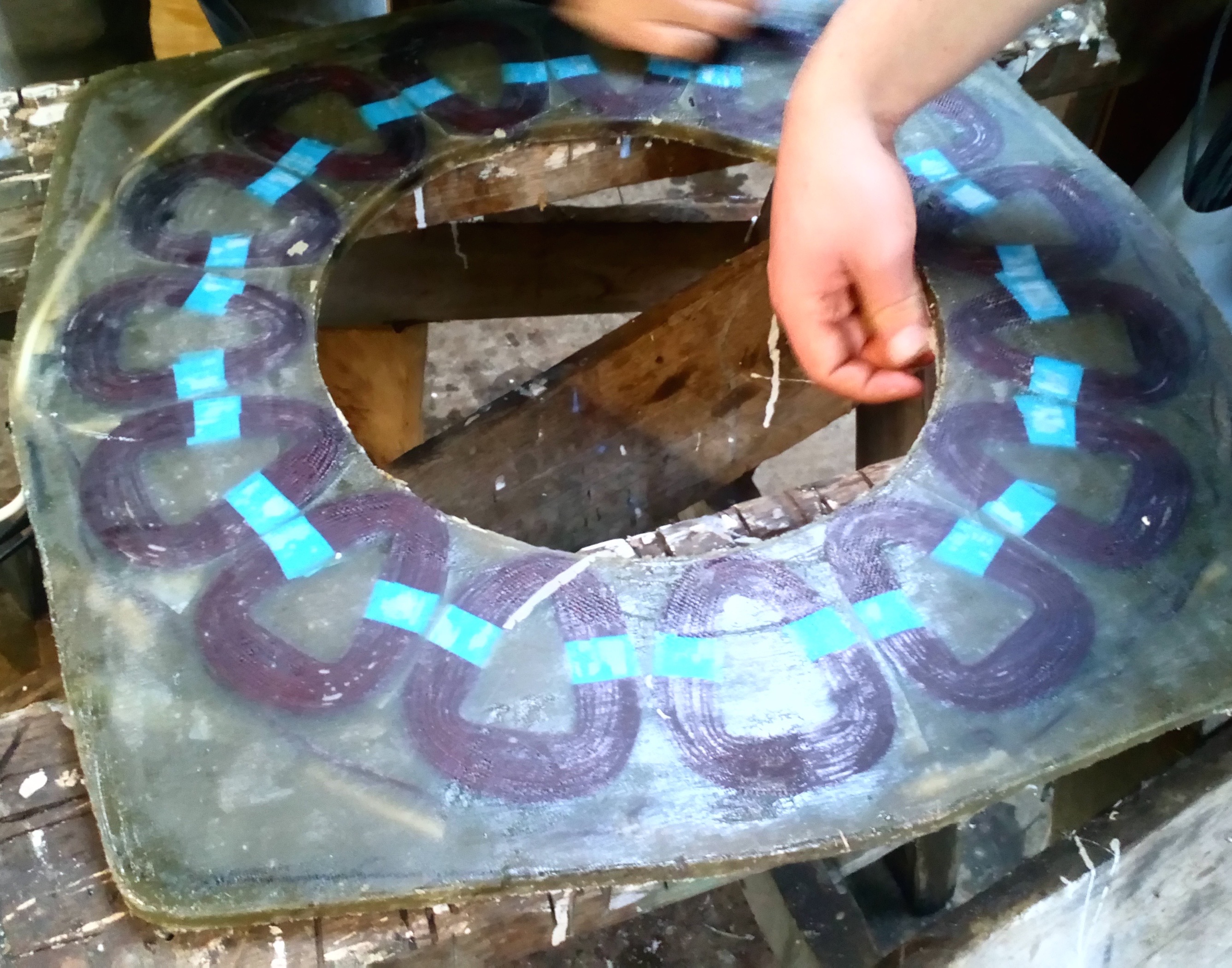
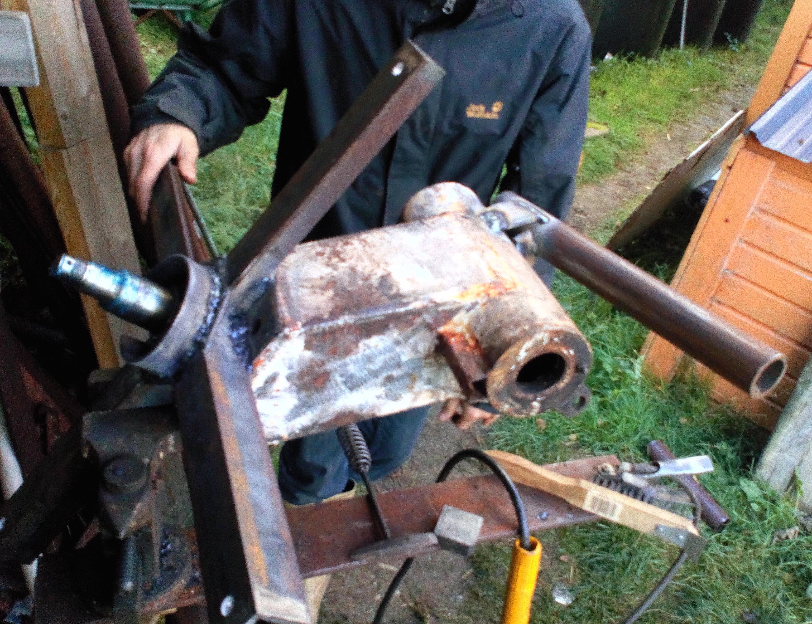
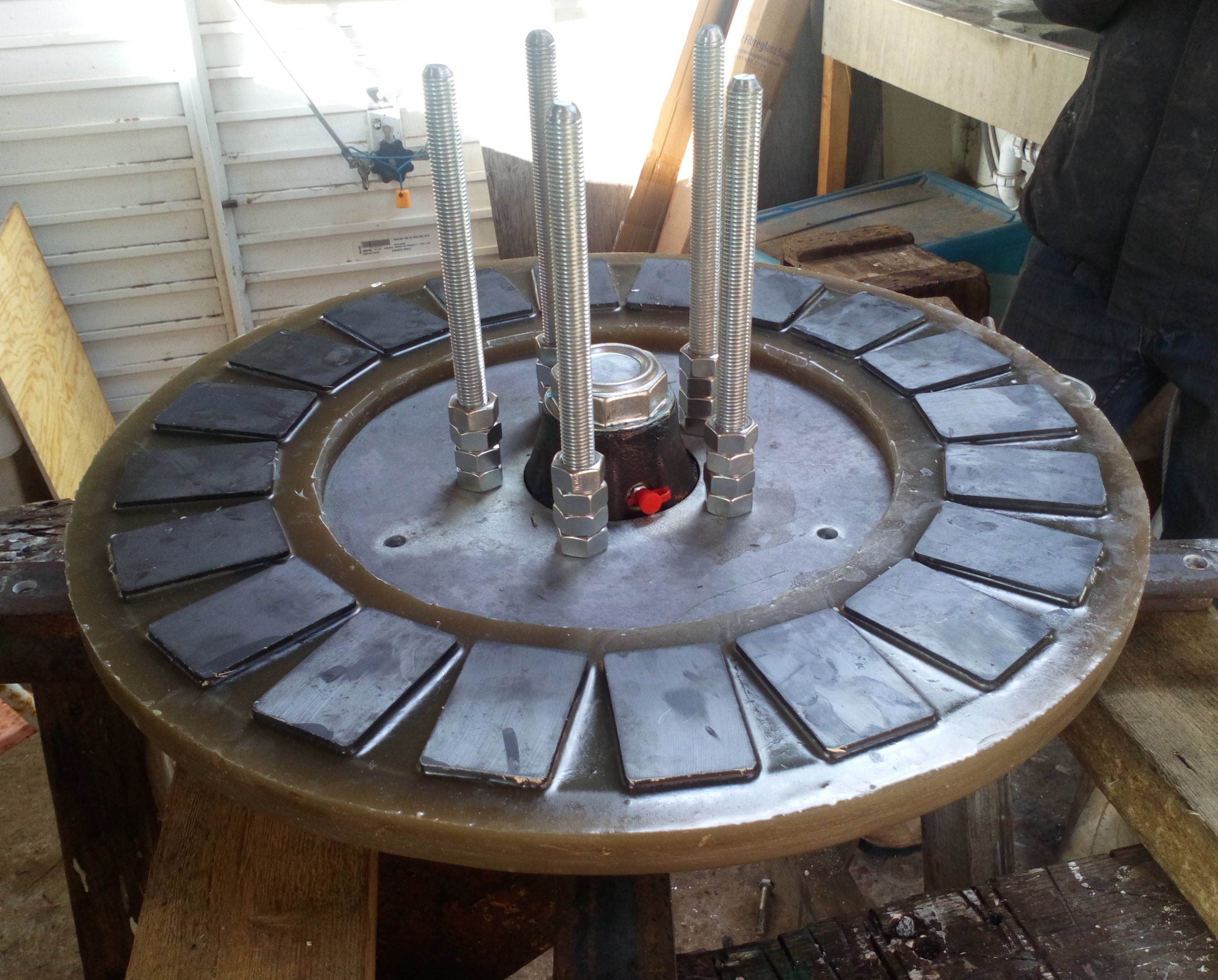
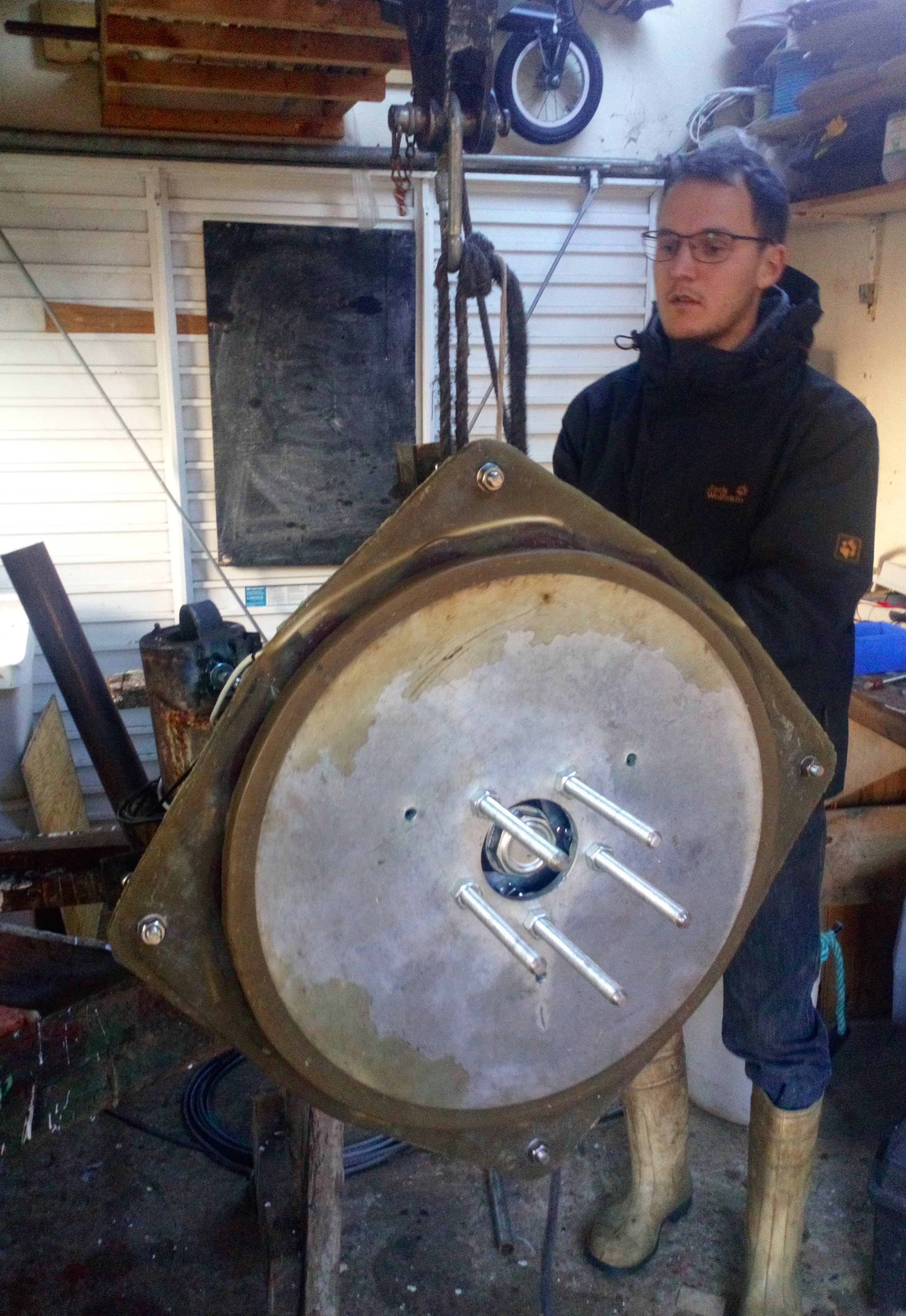
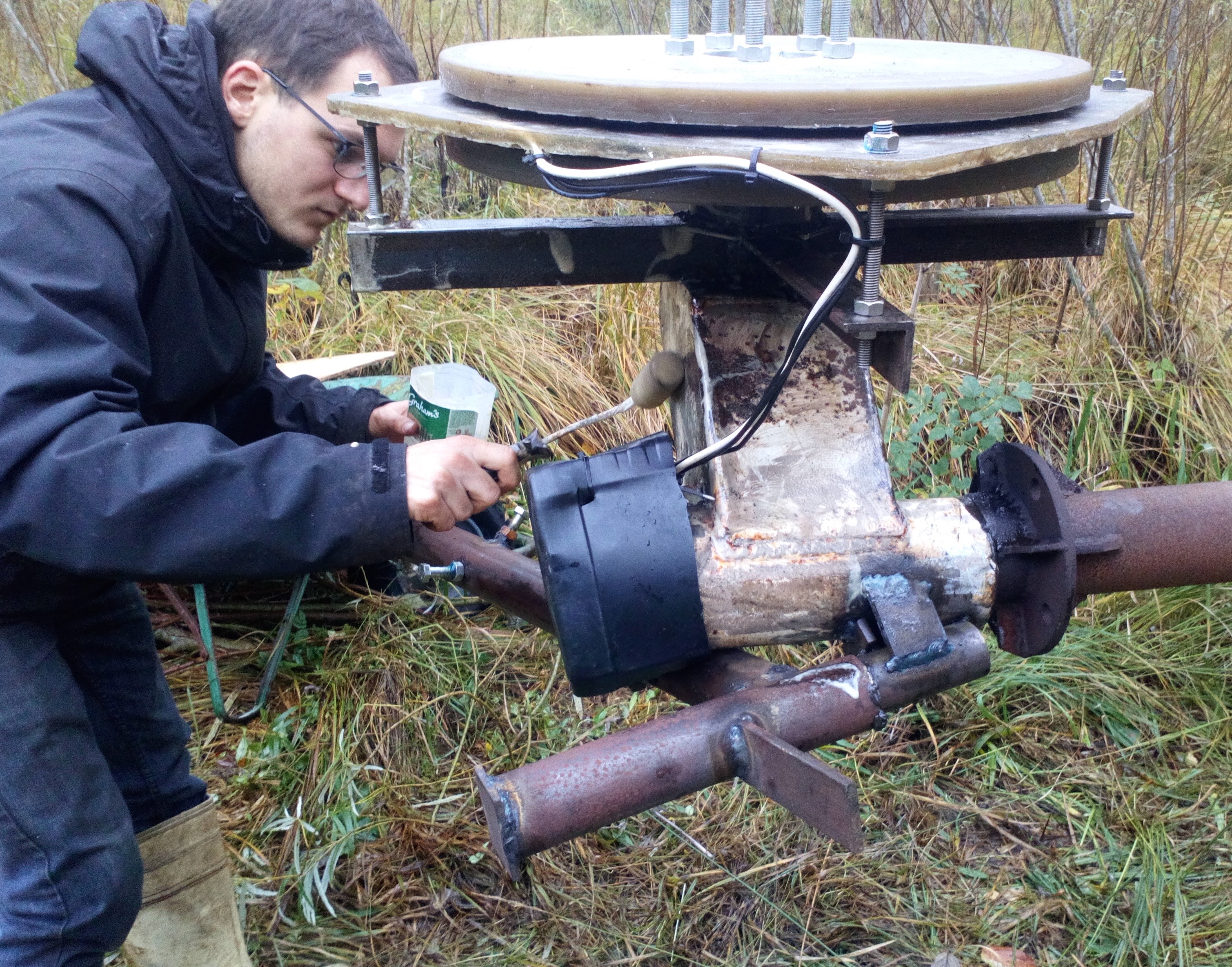
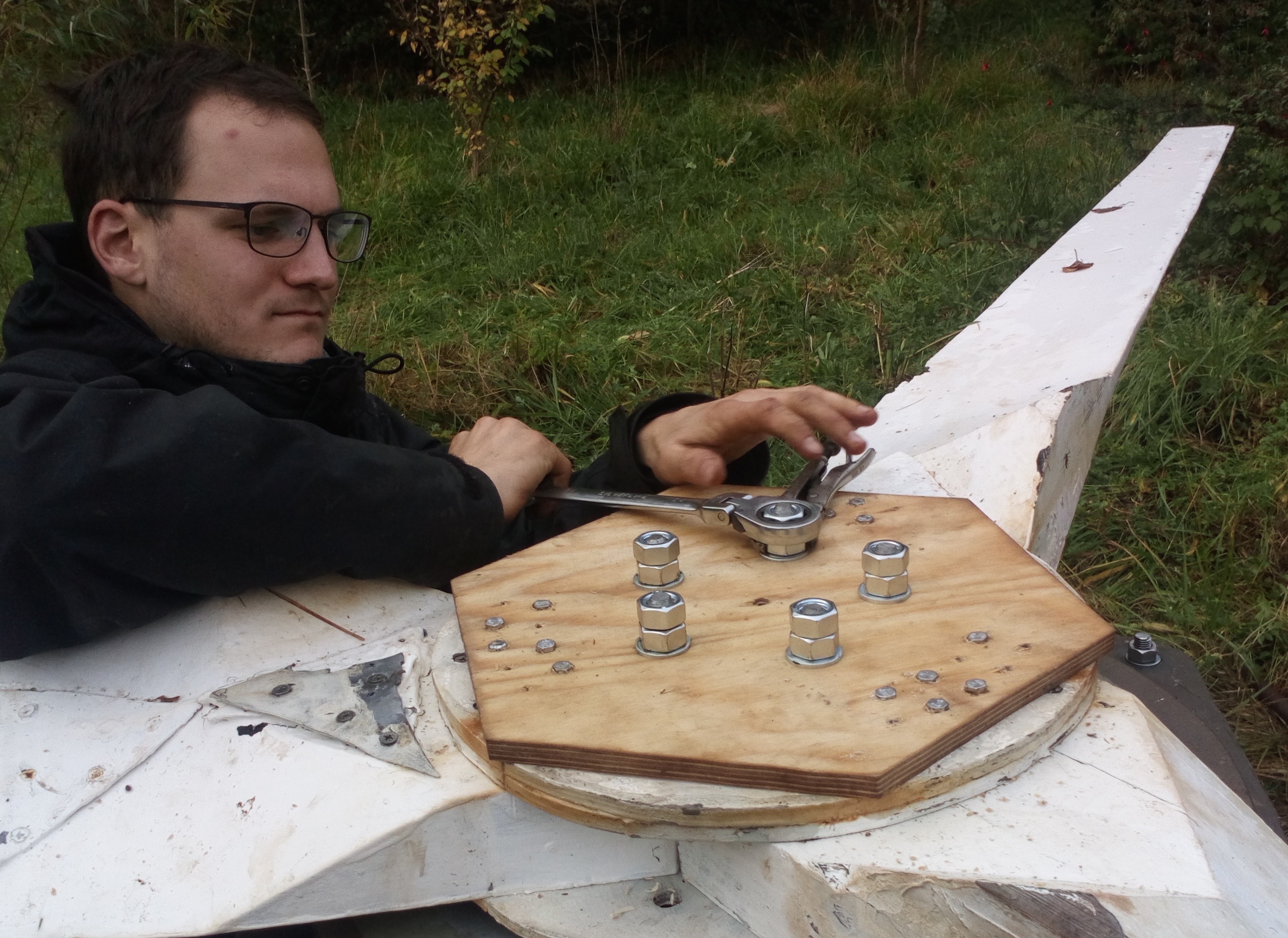
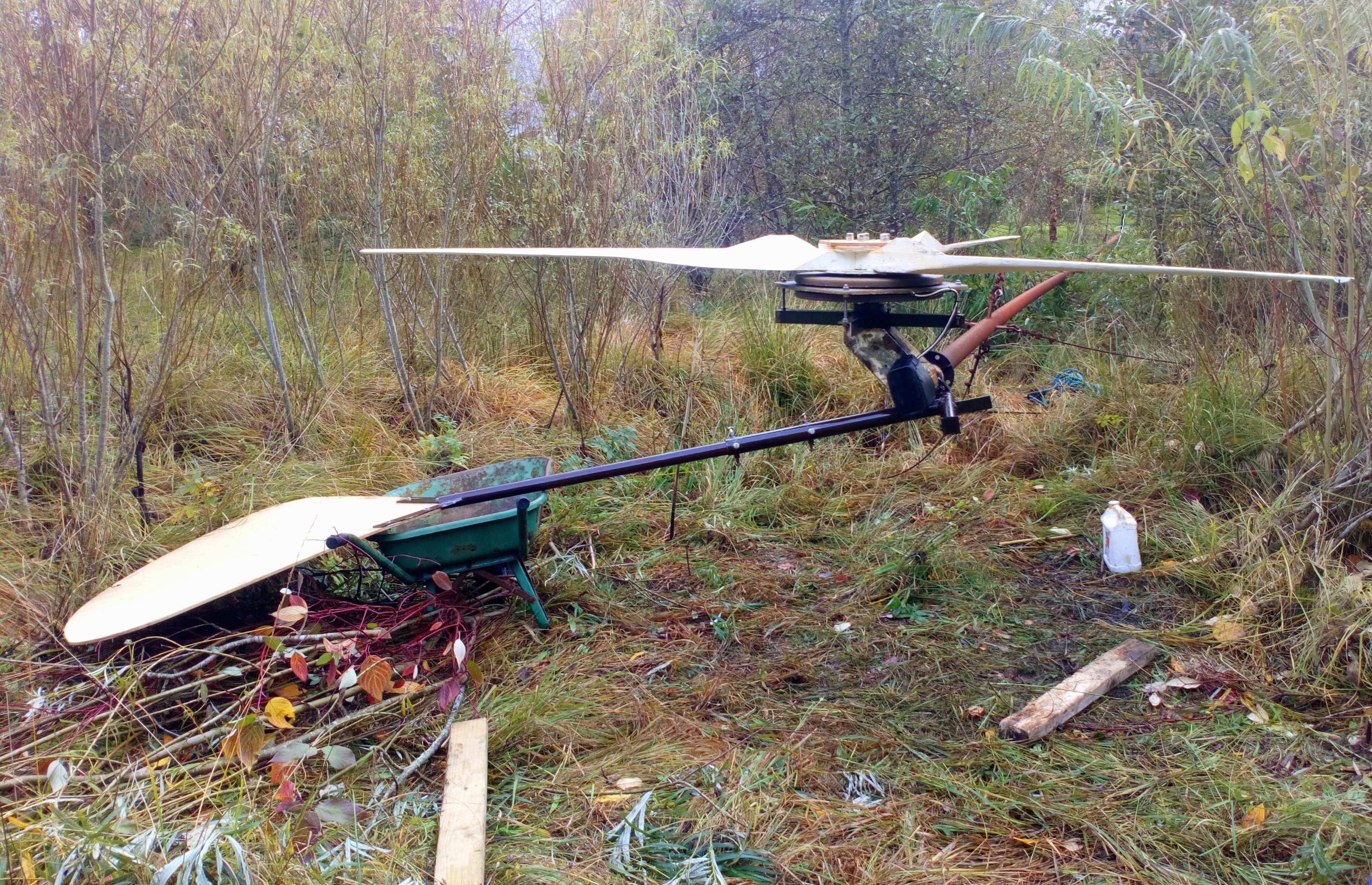
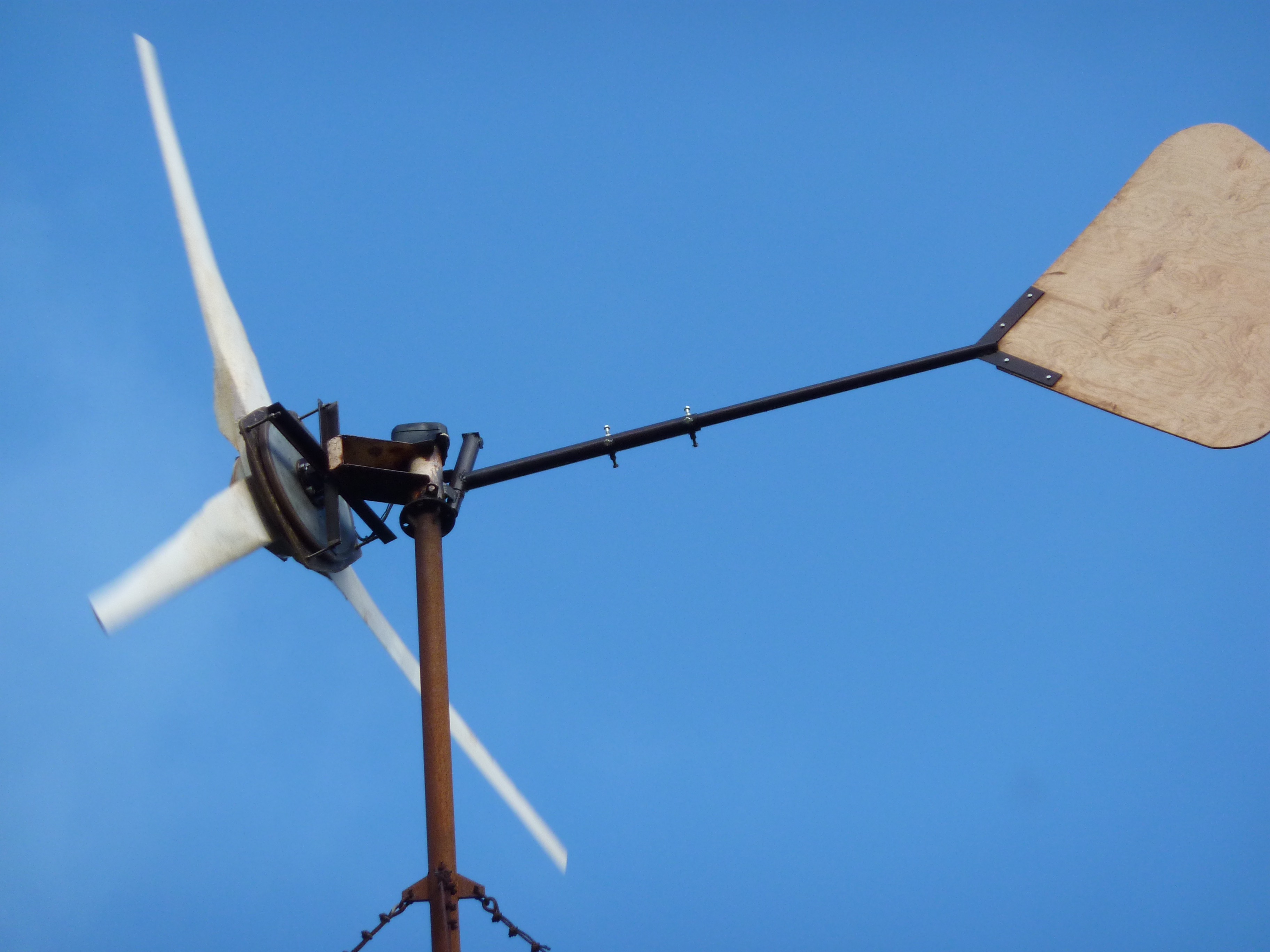
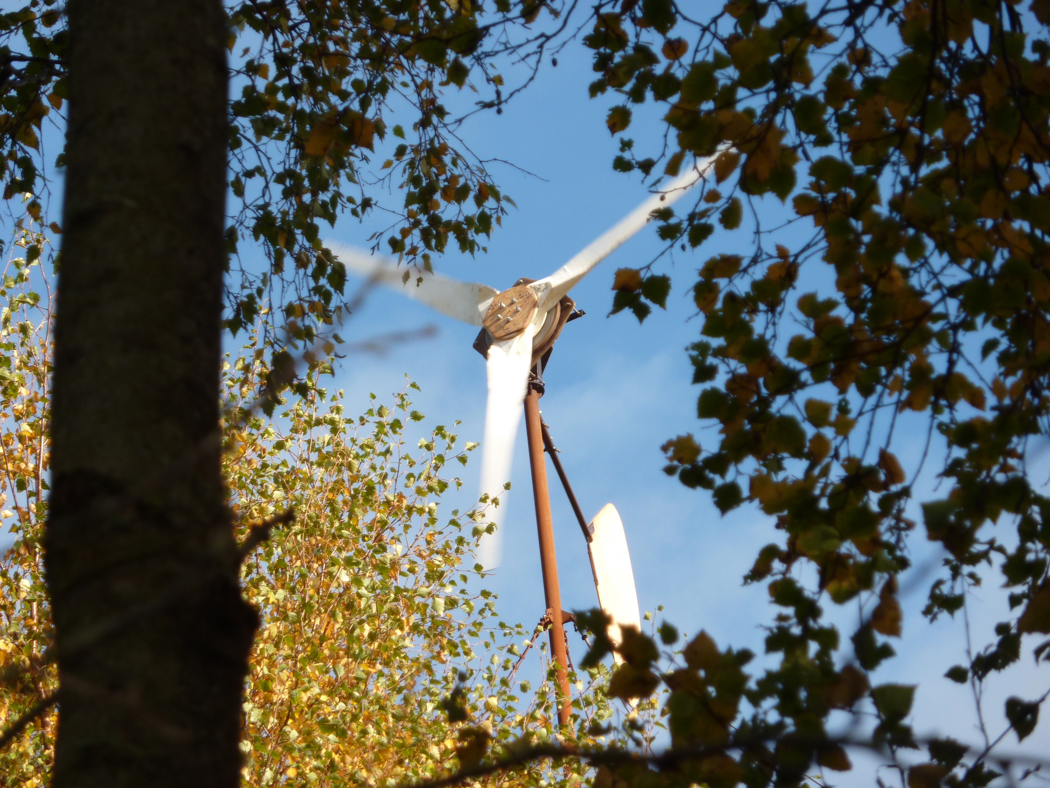
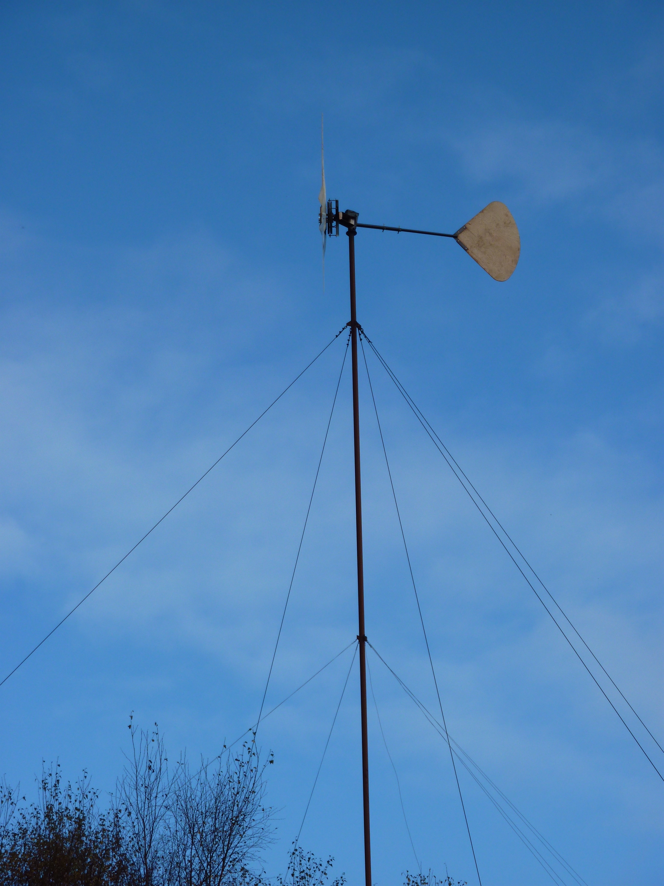
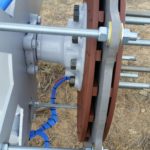
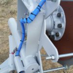
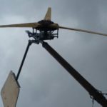
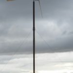
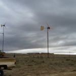
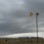
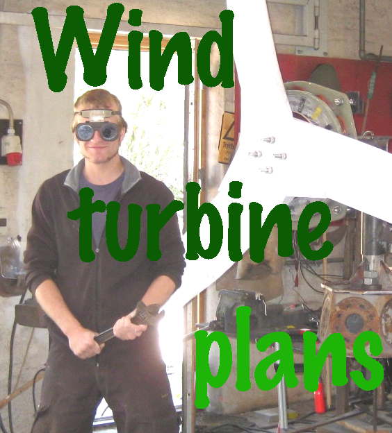
During this one week course a 600W small wind turbine with 2.4m rotor diameter will be constructed from scratch, using simple raw materials like wood for the blades, steel for the mounting frame and tail, copper wire for the coils and neodymium magnets cast in resin for the generator. The wind turbine will be the product of enthusiastic team work, as we will work in groups focusing on woodworking, metalworking and generator fabrication, along with short breaks to share what we have learned with the whole team. Woodworking will involve hand curving the blades of the rotor using drawknives and spokeshaves, planes and chisels. Metalworking will involve fabricating the steel frame to support the generator, blades and tail, with the use of welding, grinding and drilling techniques. Generator fabrication will involve winding coils, placing magnets, preparing plywood moulds and casting the stator coils and rotor magnet disks into resin. Basic woodworking and metal working skills will be taught during the course, and will enable all participants with enough hands-on experience to complete the wind turbine construction.
The course will be led in English by Kostas Latoufis. Kostas has been active in the off-grid renewable energy sector for 10 years. After completing his electrical and electronic engineering degree at the Imperial College of London (UK) in 2000, he traveled to Central America and South East Asia while also training as a silversmith. In 2004 he started working as a renewable energy researcher in the Smart Grids Research Unit (SmartRUE) of the National Technical University of Athens (NTUA). He started constructing Hugh Piggott small wind turbines in 2007 with the F.A.R.M.A. collective and continued with educational construction courses for students, in the Rural Electrification Research Group (RurERG) of the NTUA. In 2009, he co-founded the Nea Guinea not-for-profit organization, with which he has organized many small wind turbine construction courses, building windmills with rotor diameters from 1.2m to 4.2m, and many solar panel and pico-hydro construction courses. While working with Nea Guinea, he has carried out several off-grid renewable energy installations in permaculture farms in Greece and in rural development projects in Central America and East Africa. He is currently a member of the executive board of the Wind Empowerment association, a global network for the promotion of locally manufactured small wind turbines, and he is also pursuing a PhD in the NTUA on the same topic.
Detailed Program
Day 1
– Arrivals during the morning and introduction of participants
– Workshop activities (woodworking, metalworking, generator fabrication)
– Introduction to off-grid renewable energy systems (solar panels, solar pumps, wind turbines, hydro turbines)
Day 2
– Workshop activities (woodworking, metalworking, generator fabrication)
– Dinner and evening break
– Introduction to small wind turbine basics (wind energy, aerodynamics and blades)
Day 3
– Workshop activities (woodworking, metalworking, generator fabrication)
– Dinner and evening break
– Introduction to small wind turbine basics (electromagnetism and generators)
Day 4
– Workshop activities (woodworking, metalworking, generator fabrication)
– Dinner and evening break
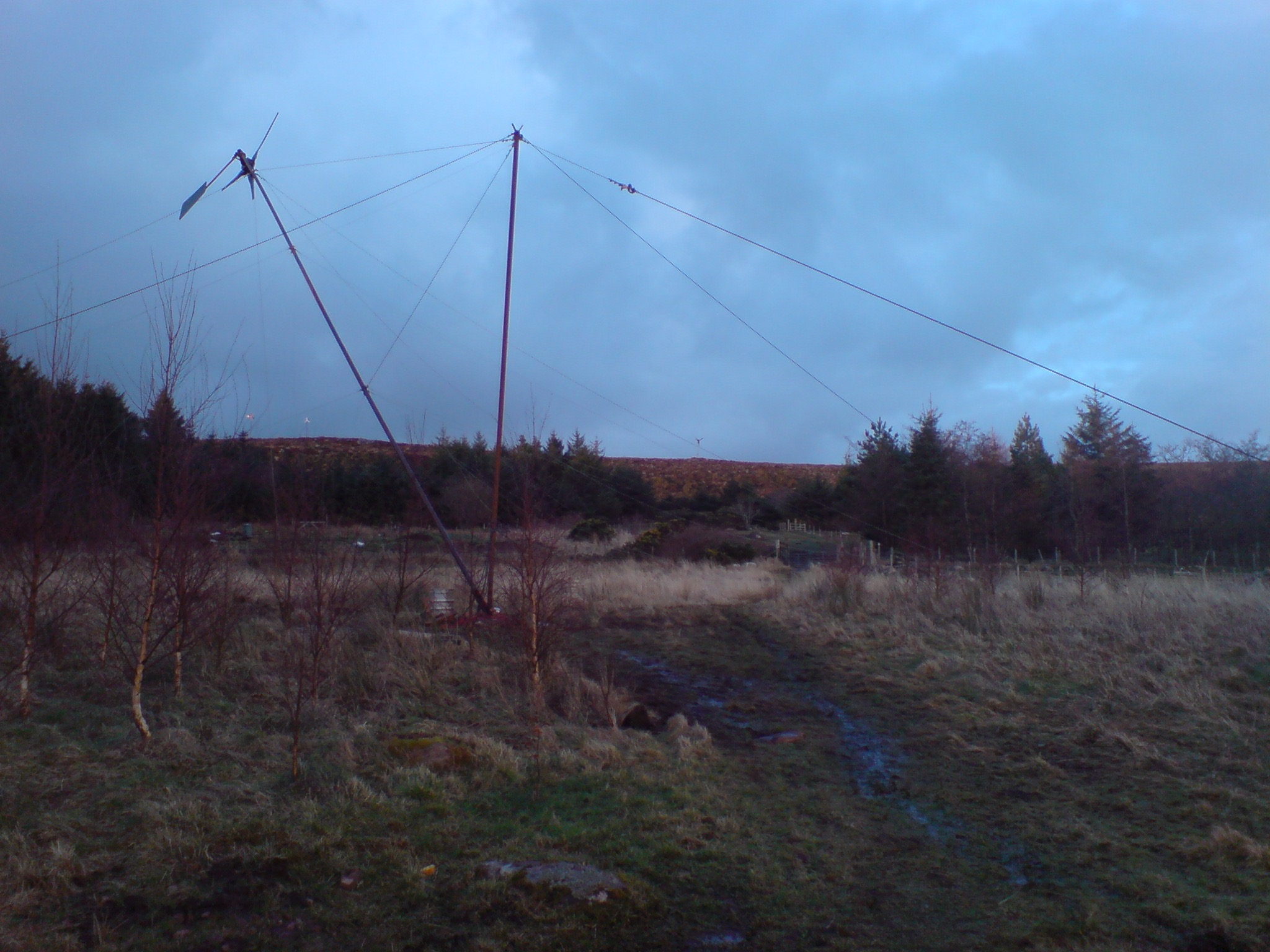
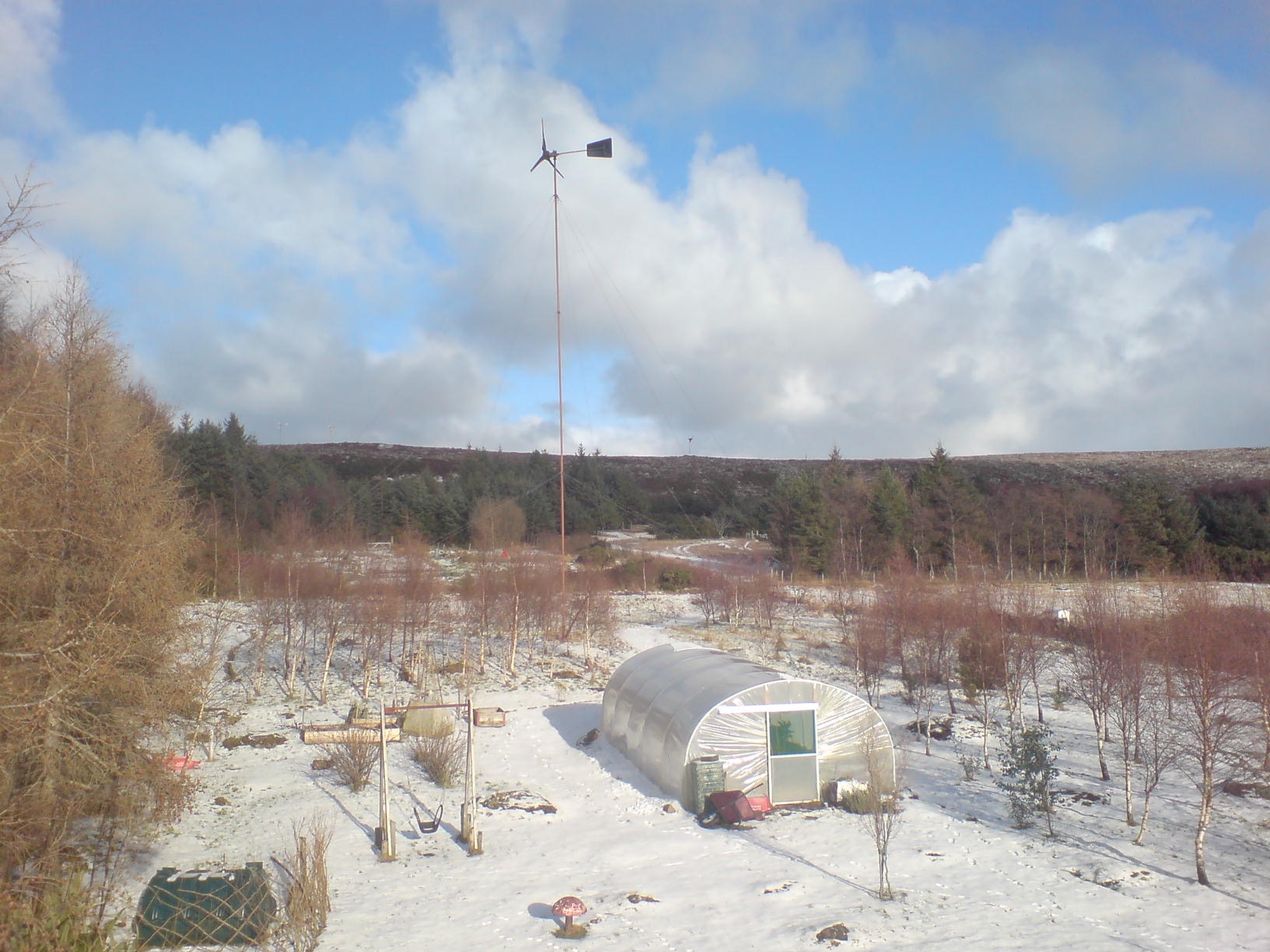
– Introduction to small wind turbine basics (furling tail system and tower installation)
Day 5
– Workshop activities (woodworking, metalworking, generator fabrication)
– Dinner and evening break
– Introduction to small wind turbine basics (electrical system and battery connection)
Day 6
– Workshop activities (woodworking, metalworking, generator fabrication)
– Dinner and evening break
Day 7
– Workshop activities (woodworking, metalworking, generator fabrication)
– Departures during the evening
General Information:
When: 21 to 27 August 2017
Where: Oficinas do Convento, Montemor-o-Novo, Alentejo, Portugal
Maximum participants: 17 persons
Prices:
Until 15 July: Full course: 250€ – Full Course + Accommodation + Meals: 320€
After 15 July: Full course: 300€ – Full Course + Accommodation + Meals: 370€
Accommodation and Meals: Oficinas do Convento have space for 15 people accomodations in a common space. Theres also the possibility of camping. Breakfast, lunch and diner are are included.
FB event: https://www.facebook.com/events/161527967716247/?ref=br_rs
Organization:
Nea Guinea: neaguinea.org/english
Cooperativa Integral Minga: mingamontemor.pt
Oficinas do Convento: oficinasdoconvento.com