
The other day I had to take this 2F windmill down because it had stopped working.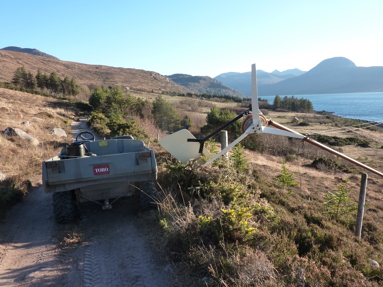 Turning slowly as if on the brake. It’s a few years old and I thought most likely the flexible wiring inside the tower had got twisted up a bit and somehow shorted out, although the wires did not look that bad a ground level.
I was pretty shocked when I saw it close up, because the plywood had somehow got shattered at the front. 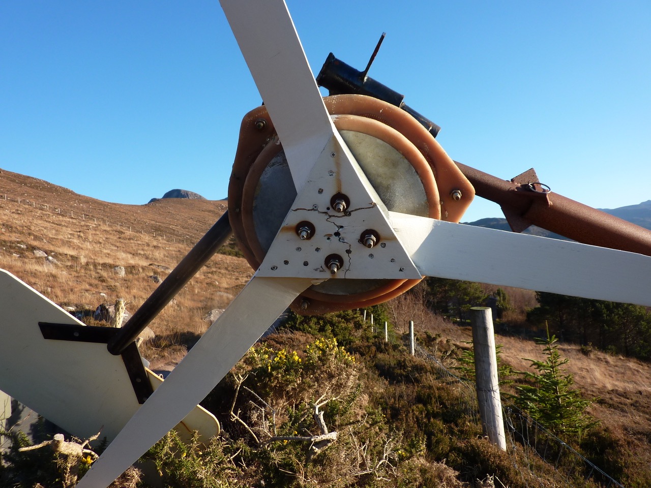 Birch plywood is very strong, but I suppose I was pushing it a bit to use 9mm ply here. It’s not the oldest 2F on Scoraig using that plywood but it definitely taught me something. Always more to learn!
I replaced the 9mm with 12mm birch. I figured out a quick way to lay out the screw holes in the plywood so they are neat and symmetrical, and avoid the bolt holes for the mounting studs. I used a cardboard template that matches the shape of the contact area between blade and ply. (Click to see larger images.)
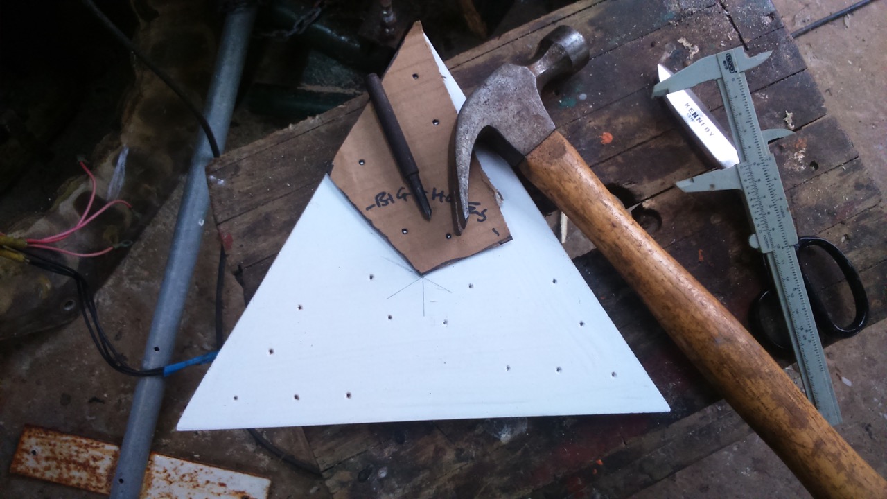
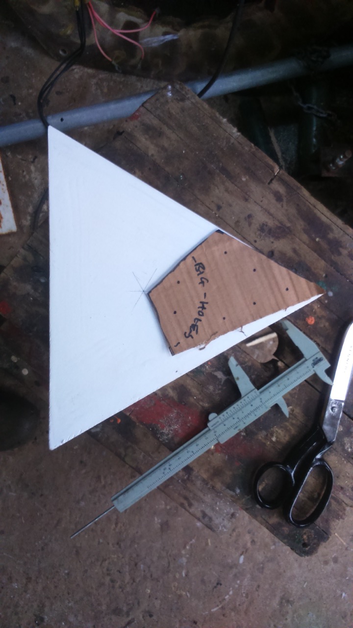
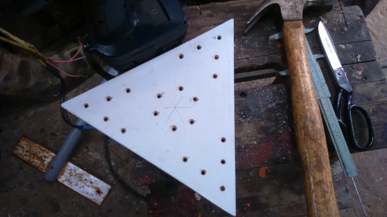
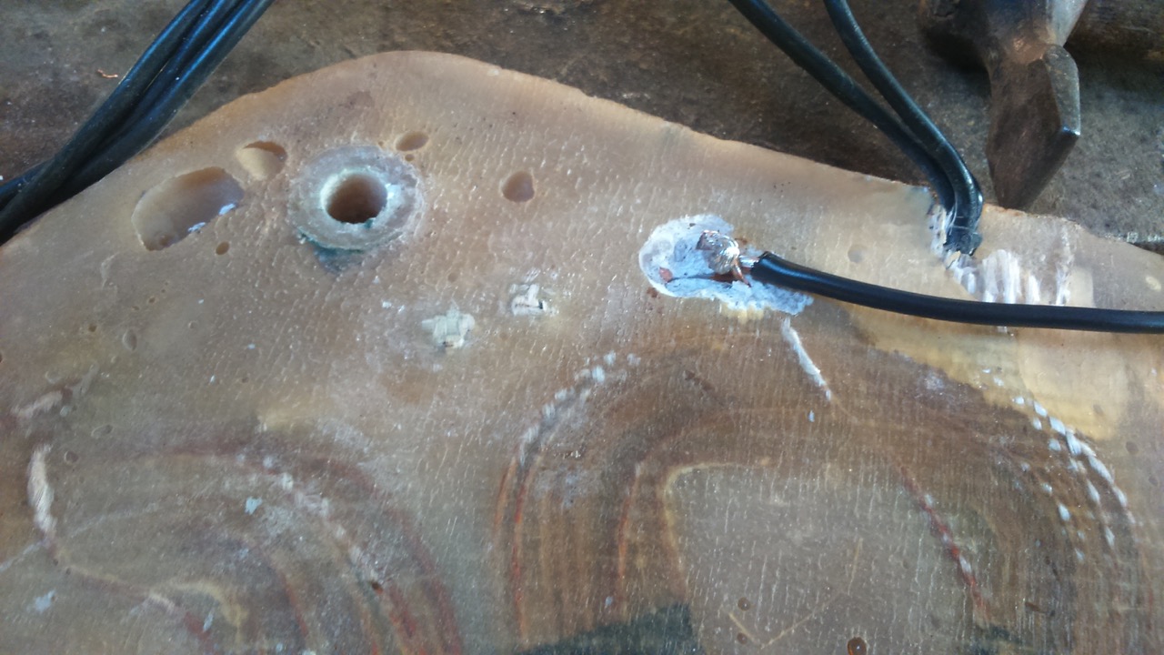
Punching through the dots on the cardboard gave me my hole centres for drilling. Next I went looking for the shorted wiring. But I found to my horror that the alternator was “braked” even when totally disconnected from the wiring, so the short was internal. Maybe I needed to make a new stator?
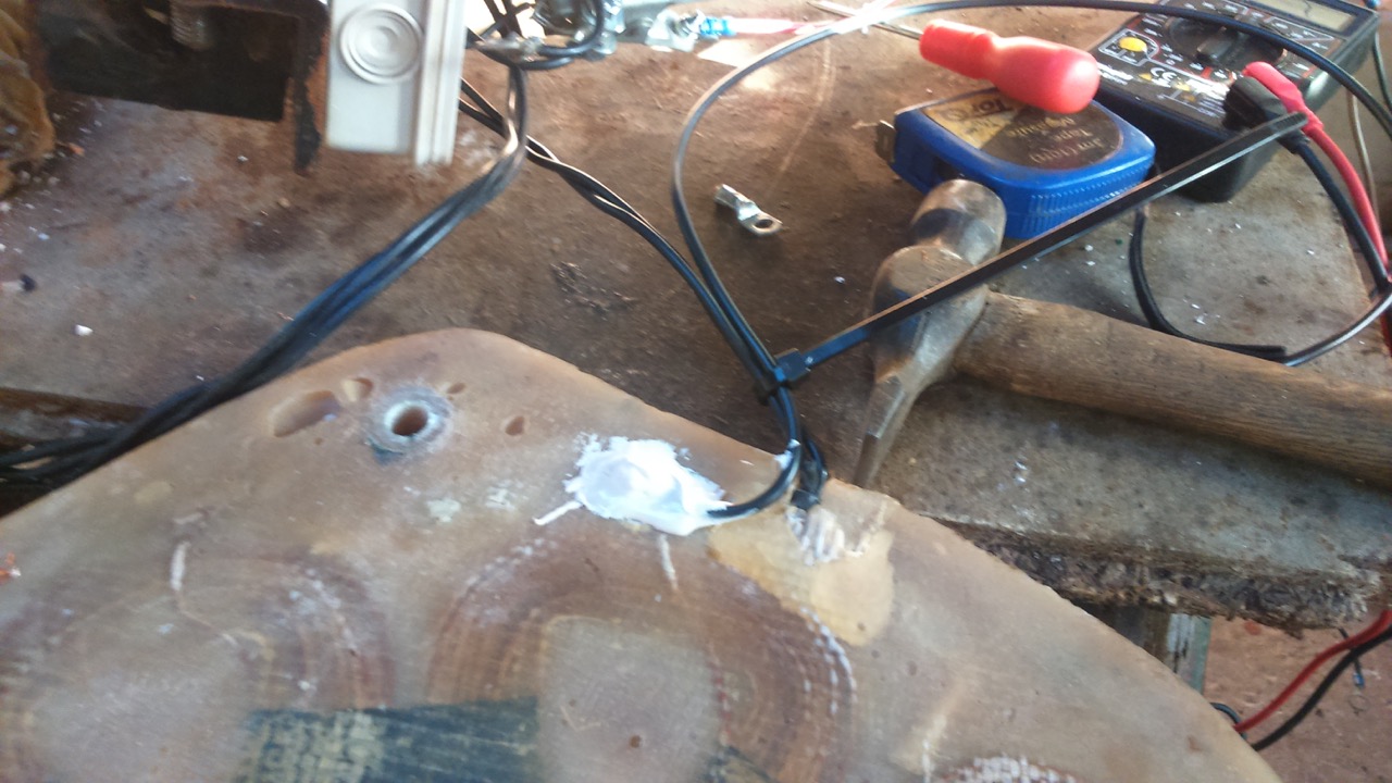
First I set to work to find the location of the short. I used a battery, a magnet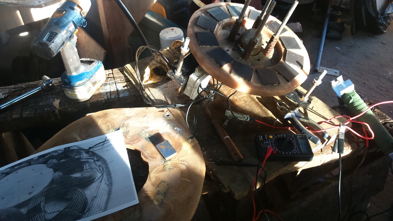 and a photo that I miraculously found of the stator before it was cast (back in 2013).
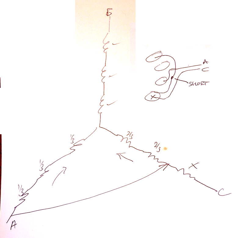
Passing current through the coils between each pair of wires gives rise to a pattern of attraction and repulsion of the magnet in the winding that reveals where the current is going. (Usually this will be “push, pull, nothing, push, pull, nothing, push, pull, nothing.”) One pair of wires gave rise to a very strong field in just one coil and the photo revealed where the short must be between the output wire off a neighbouring coil and a series connection from that coil to the next.
The fact that it was a fault on an incoming wire meant I could simply cut that wire and make a new incoming connection to the first coil in phase A where the wire comes close to the surface of the casting to enter the coil. So there was not too much digging around to do in the resin (using a drill and a gouge).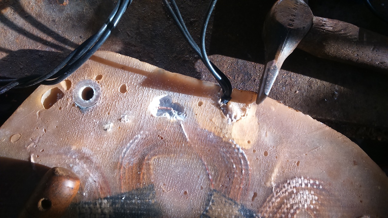
That was pretty lucky, and a quick solder joint had it all sorted out.
Balanced the blades, greased the bearings, untwisted the tower wires with a cordless drill and got the machine back into action after a relatively painless repair considering how much worse it could have been!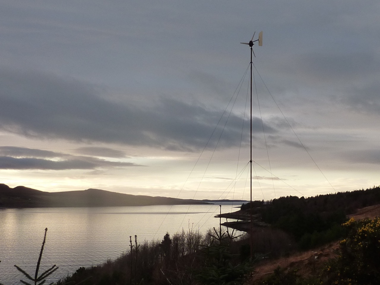
Not a breath of wind of course.

Ah the Gods were smiling on you today. Nice job.
I have made a slight modification to your design for the hub stud holes. Having found that removing and refitting the blades was a bit of a fight on occasion i have drilled the mounting holes out slightly and fitted a sleeve of 15mm copper to each hole. I set the copper below the faces of the 2 plywood discs to allow for compression as the nuts are tightened.
The hub is now an “easy friction” fit onto the studs. I did this mod over a year ago and there’s been no movement in the blades to date.
Yeah, andy, I use a very precisely fitting hole pattern in the back plywood disk and then over-sized holes through the rest of the assembly. This is fairly easy to remove and replace onto the studs. The plywood and screws hold the assembly together (or not, it seems!) whereas the mounting holes simply keep it all centred and the nuts clamp it firmly back onto supporting washers at the back.
cheers
Hugh