Here is a piece I did about AC and DC in 1999. It explains why DC wiring is slightly more efficient than 3-phase AC wiring where the AC is feeding a rectifier (rather than grid AC which is at higher voltage). One way to understand why AC is less efficient is to notice that Ac current is intermittent, only using the wire part of the time, whereas DC uses it all the time. So for the same peak voltage, DC is going to work better.
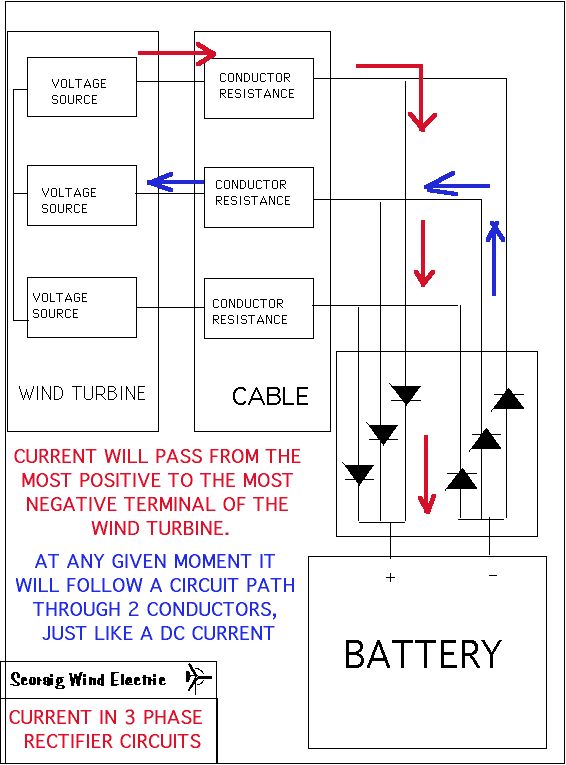
There is some confusion about how to calculate losses in the cables of a 3 phase wind system. If the 3 wires are feeding a rectifier, charging a battery, then the current in the cables is dominated by the need to supply DC at battery voltage to the load.
The cables may change, but the current tends to remain constant.
Paul Gipe’s question
What is the power lost in conductors from a 850 Watt permanent-magnet, three-phase alternator feeding a diode bridge rectifier delivering a nominal 24 VDC to a battery bank. The rpm, voltage, and current of the three-phase alternator varies with wind speed. There are three cables (conductors) between the wind turbine’s alternator and the diode bridge. There are two conductors from the diode bridge to the batteries. The conductors are #8 AWG with an AC resistance of 0.78 Ohms/1000 feet. There is 150 feet from the wind turbine to the diode bridge, and an insignificant distance from the diode bridge to the batteries.
The DC current is found by dividing watts by volts. this gives 850/24 = 35 amps.
If you want to analyse situation mathematically, current in each conductor is 35 amps for 2/3 of the time. The rms current in each conductor is therefore (2/3)^.5=0.82 times 35 amps = 29 amps (rms). Resistance of each conductor is 0.78 times the cable run of 150/1000 feet, giving 0.117 ohms.
Power loss is I^2*0.117
which is 2/3*35^2*0.117
which is 1/3*35^2*.234 for each conductor
which is 35^2*.234=287W in total.
This is a 34% loss!
An easier way to analyse the situation (which also give the same answer) is to say that at any given instant the DC current 35 amps is flowing around a circuit path with resistance equal to 0.78*(cable run in feet/1000). Cable run is 300 feet for the full circuit.
Finally I should point out that the above is strictly only true if the internal loss is small. As loss increases, the situation becomes much more complex, since more than 2 wires will start to conduct at once during the changeover. But the above answer will be accurate enough for practical purposes, given that we are arguing about such large differences in our answers.
Hugh
October 1999

Hello Hugh,
I am trying to work out the cable size i need for 24 volt 3 phase 1000 Watt wind turbine.
1000 Watt divided by 24 volts gives 41.66 Amps.
From memory, from a long time ago one phase will be positive while the other two are negative. Question If turbine was supplying max load would that one positive wire be carrying full 41.66 Amps. If so I would need 25m2 cable. Am I right or have I missed something. ?
I want to bring 3 phase down to the battery room rectify it there to DC , controller brake, dump load etc.
Regards Paul.
I disagree with this statement:
“…
One way to understand why AC is less efficient is to notice that Ac current is intermittent, only using the wire part of the time, whereas DC uses it all the time
…”
Since the AC Voltage produced by the 3 Phases is clamped down to the Battery Bank Voltage, you will have either:
Scenario #1 …
One Phase with a (+) voltage and two phases with a (-) voltage. The two phases with the (-) voltage will SHARE the return Amps from the (+) phase. This “sharing” reduces the amps flowing in the two (-) phases and will reduce their I x I x R Wire Losses.
Scenario #2 …
One Phase with a (-) voltage and two phases with a (+) voltage. The two phases with the (+) voltage will SHARE the return Amps from the (-) phase. This “sharing” reduces the amps flowing in the two (+) phases and will reduce their I x I x R Wire Losses.
NOTE – The Open Circuit Phase Voltage is significantly higher than the battery bank voltage. Therefore, the AC waveform is CLAMPED down to lower voltage for a significant amount of time, which allows for “SHARING” of the amps between the 2 phases that have the same polarity.
Reducing the I x I x R Wire Losses makes 3-Phase AC more efficient than DC.
In addition, 3-Phase AC, High Voltage, Low Amperage MPPT is even more efficient than any direct connect to battery bank
Could somebody tell me how are you physically measure the three wise output on an acWind turbine to make sure that each wire is generating electricity where do you put the cables coming from the Avo meter thanks Dave
The best way to measure current is to use a “clamp meter” (for example Uni-Trend UT203) and clip it onto the wire. If you do not possess one of these then you must interrupt the wire and insert an ammeter which could be as simple as a small resistance shunt that you then measure voltage across to arrive at a measure of current. Sometimes for approximate readings I use a piece of copper wire in the circuit, and measure the mV drop across it to assess the DC current in A. (The calculation involves estimating te resistivity of copper at ambient temperature.) It’s harder to measure very small AC voltages though so this is not ideal for AC currents.
Wow hugh your have allot of trial and error time in your age . I.hope someday to learn as much wisdom I am still aging. I love to read and build anything solar or wind or steam and water geothermal tech is amazing. Imagine the day humans could use body head to power tech.shared genetics drives, imagine sharing a genetic energy running through one sourse a spinning shaft. A natural hot spring supplies a 24/7 very high pressure man made line with a steam turbine under thousands of pounds of pressure turning a turbine turning a long shaft. With sprockets running with arms out spinning like a turbine. Supported like a turbine a bearing supports mounted inside a bracket spinning long shaft. More sprockets contacting multiple PMA, charging banks by running inline inverters or step ups powering a duel bank 250 amp charger or a duel bank 80 amp marine charger or no batteries just inline inverter that supplies constant 220v or 110v 120v and just runs forever. Lots of cool ideas. I am still figuring out my 3 phase turbine that is portable tower and 1410 ah bank with solar and hardwired 50 amp port with 30 amp rv box. It works good turbine seems like it has to spin way to fast to make power. I wish I had a PMA that could provide more power at lower wind speed.
“no batteries just inline inverter that supplies constant 220v or 110v 120v and just runs forever.” Unfortunately, perpetual motion will not work 🙁
” I wish I had a PMA that could provide more power at lower wind speed.” Yes this is what you need and you will find that the solution is to use plenty of magnets on large disks because this solves the problem. It helps to use a blade design that runs fairly fast in the first place.
planning to assemble vertical wind turbine 24 magnet at 9 coil nothing know about computation how will be my output current at 24 volts coil is about 70 turns gauge size of 14. thank you
hi, i need your help i am from philippines and i saw your publish of three phase generator i preparing to install 24 magnets in 9 coil it is possible to work? i used in coil Gauge 14 and turn about 70 turns of coil i am wondering how many current will be my output for 24 volts at my turbine using vertical sorry to my english and grammar . Thank you very much specially if you give an advise to my work and i learn connection that you publish 20/04/15 thanks again
hi Renato,
It is normal to use 9 coils in the stator with 12 magnets on each disk. If you have 24 magnets on each disk then you need 18 coils. To be able to help you I need to know the size of the magnets and also the rpm at which the turbine works. I think you made a big mistake using vertical axis. But you can read more about that somewhere else.
cheers
Hugh
Well, then for this novice, it begs the question:
Is it more efficient to rectify the ac at the alternator and send dc down the pole to the charge regulator? Of course this would result in more expense in thicker cable, but it looks like you would need to do that with ac cable anyways. 34% energy loss one heck of a loss to pay for, no matter jow you look at it; heavier gauge ac or dc cables or inceasing alternator size thus possibly needing to increase overal turbine size.
Hughe maybe you can give us some positive advice?
Thanks,
Scott
hi
To be honest I mostly use 3-phase transmission so that I can have the brake switch at the house and brake on the AC side but for long cables I often put the rectifier at the turbine or at the base of the tower and use DC for most or all of the wire run. This is because it uses less copper and/or wastes less power that way.
Another piece of advice on this is that if your alternator is super-efficient axial and your wires are very thick you may stall the blades so it’s better to have some loss in the transmission cable anyway or you may stall the blades, and lose out that way. But it’s cheaper to use DC than 3-phase AC as you only need 2 wires and it has roughly the same loss for the same size per wire.
Have fun
Hugh