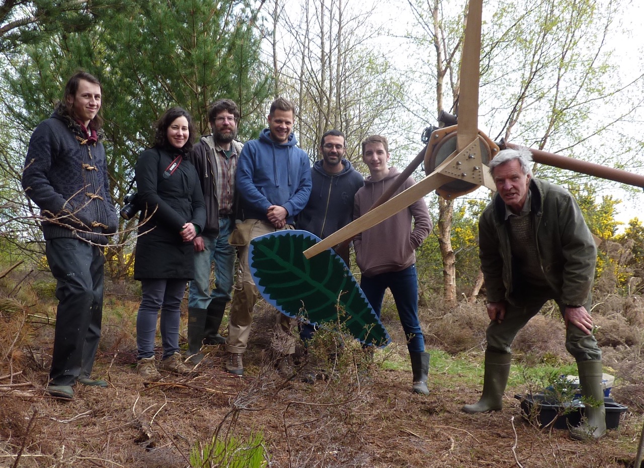
The self-timer group photo session.
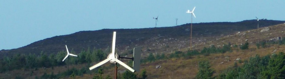
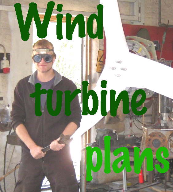
On this year’s course we built a 2F machine but with 16 magnets instead of the usual 12. I have a cheap source of these smaller magnets. The 2F is a “2 metre diameter Ferrite magnet wind turbine” which is documented in my 2F wind turbine construction manual.
The rpm is a little higher than the 12-pole version. We played with adding an extra layer of magnets to one rotor, and got about 15% higher flux density (hence lower rpm) but I don’t think I will build any serious alternators stacked like that.
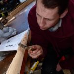
Most of the blade carving was done with drawknives but I did not get any pics of that. It’s an easier procedure than the one in my Recipe Book and seems to give good results for this size of turbine.
I am very grateful to Kostas Latoufis for coming to help, and for putting up with me so patiently. Also grateful to the five participants for their hard work and good company.
-
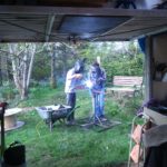
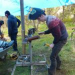
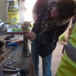
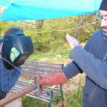
- Welding practice
-
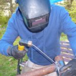
- Owain welds the stub axle in
-
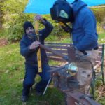
- Theo welds the yaw bearing
-

- Annabel welding
-

- Kostas sets up the tail hinge angle
-

- Theo helps with the tail hinge angles
-

- More angles
-

- Using a 6mm drill bit as packing to check that the tail hinge is above the yaw axis
-
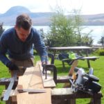
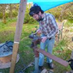
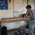
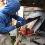
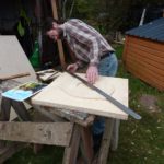
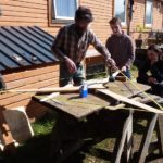
- JP sets up a fence to cut the blade taper
-
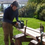
- Tapering the blade
-
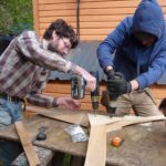
- Owaing kerfing his blade
-
- and chopping out the waste wood
-
- Using a chisel to smooth the triangular ramp.
-
- Removing the tip in the end
-
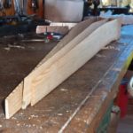
- Some blades came out a bit undersized
-
- Sam building up his blade with epoxy
-
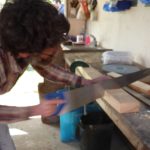
- JP cuts the root of his blade to fit the hub.
-
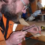
- Annabel checks the thickness of her blade root
-
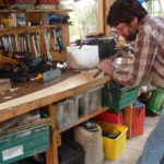
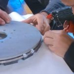
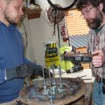
- Marking out the holes for the coil winder
-
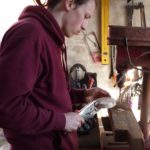
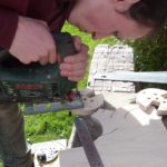
- Sam drills holes
-
- Cutting notches for tape
-

- One coil winder.
-
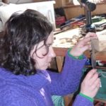
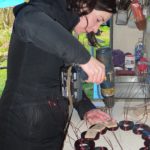
- Winding coils
-
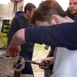
- Taping a coil.
-
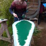
- The stator mould
-
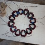
- 12 coils the right shape and size ready.
-
- Fixing in place to solder tails.
-
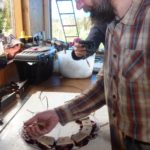
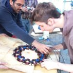
- Owain checks polarity using a magnet with a current in the wires.
-
- Kostas and Theo put coils in mould.
-

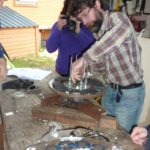
- Out comes the stator
-
- Hot glue gun to fix the stainless wires around the magnets
-
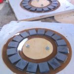
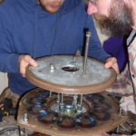
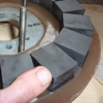
- 16 pole magnet rotors in the moulds
-
- Owain assembles the alternator
-
- JP fits the second rotor.
-
- Extra magnets on one rotor.
-
- Playing with an extra set of magnets on one rotor.
-
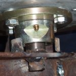
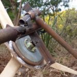
- Hub assembled in reverse so we can access the grease nipple.
-
- Checking clearances
-
- JP welding the tail
-
- kostas helps JP with tail welding
-
- Theo paints the tail (a leaf)
-
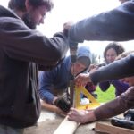
- Assembling the blades
-
- Stainless steel coach bolts this time
-
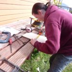
- Drilling clearance holes
-
- The blades did not need any balance weights!
-
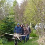
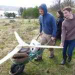
- Off to put up a windmill.
-
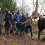
- The self-timer group photo session.
-

- Annabel cranks the rope hoist.
-
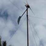
- Up and running!
-
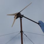
- Another beautiful windmill spins.
Looks like a fun time.
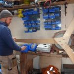
just one question…Given that you are off-grid, did you use your system’s batteries to do the welding -I know that some people do that- or did you use a gas generator ?
hi David,
Yes we use the batteries and inverter to weld. Much better than a generator. Silent and smooth with instant power response. for many years I used a generator and it’s great to now have a big enough system to comfortably weld with it. A decent 48V battery and a 3kW inverter is all you need to run an inverter/welder (much more efficient than the old buzz box type). I have had many engine-based welders over the years but using renewables is by far better.
cheers
Hugh
Interesting…I use an inverter welder, myself, and I like it very much; small, light, DC output and it does a great job. When asking myself about welding with wind/solar, I’ve always considered the straight-off-the-battery approach but I like your approach more. It’s not as messy and, unlike an engine-welder, it’s not running even when you’re not striking an arc.
years ago when we were running on wind, I had rebuilt a two-cylinder Wisconsin engine and I teamed it up with a 200A, 24 v aircraft generator for welding. It worked very well but had I set it up to dump charge into the batteries when not actually striking an arc, I could have justified it a bit better. I definitely prefer your idea and I’ll file it away for future use.
Lovely to see that well done