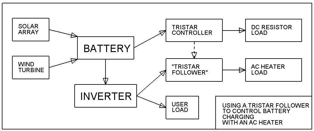
 The Tristar controllers that I use for managing the charge rate in battery systems are very sophisticated, microprocessor controlled devices that very intelligently decide the best voltage for the battery and then proceed to divert any excess power so as to charge the battery at exactly that voltage. I love them because they are rugged and reliable. You can program them with switches or with a laptop. But the heaters that they run work at battery voltage and they do make a buzzing noise that is not always welcome in a living space.
Here is a tr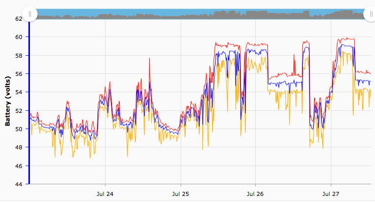 ace of my battery voltage to show how the Tristar manages to hold its maximum value steady when the wind and sun are strong, and to step it from absorb (58V) down to float (55V) level when the battery is well enough charged.
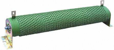 Here is a picture of a typical resistor used for dumping surplus power into “space heating”.
I have a couple under my bath tub, but pretty often people keep them out in the shed because not everyone thinks that the buzzing sound they make is pure music, like me.
You can buy a special low voltage water heater to run at battery voltage, and I have one of them too. But it’s a headache to consider what will happen when the water gets too hot. Thermostats don’t enjoy switching high DC currents like 45 amps. The heaters are costly and the wiring has to be specially thick too.
Phase control solid state relay
That’s why I am very pleased to have figured out how to use conventional AC grid-voltage water heaters (and other AC heaters) to divert power smoothly from the battery using a Tristar and an inverter.
 I use “
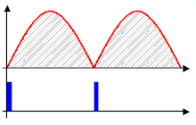 phase control” to do this trick. (I stole this gif from wikipedia to show the principle of how delayed phase angle switching can modulate the power to the heater. )
Crydom make very nice”phase control” Solid state relays (SSR) and I buy the 50A rated ones to be on the safe side even for switching 13 amps or less of AC current. You feed it with 2-10Vdc input, and it uses phase control to ramp the AC output (inverter to heater) from 0-100% duty.
The voltage across the Tristar’s DC load resistor on duty looks like this, roughly. 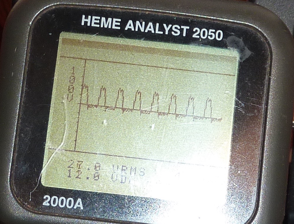 A series of 55V (or 58V) pulses. As soon as the battery reaches at the target voltage, you get the full 55V at the heater, but only for very short pulses at first, getting longer as we need to divert more power, until the heater is on full time (if you have that much power coming in that the battery has no use for.)
55V is too high a voltage and would destroy the Crydom MCPC2450C input if you were to hook its input up directly to the DC heater. The SSR can only handle 32 volts DC on the input. It needs 8-32V and about 14mA of current to power its brain and it needs 0-10V and about 1mA of current to tickle its control input.
Tristar Follower
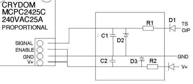 Consequently I had to invent a really cool driver circuit which I am sharing with the world now (just because I am a sharing person I hope you notice) and this is how it works. I have about ten of these already built and out there working well.
Ground (battery minus) is connected to the ground terminal of the SSR.
V+ and ‘enable’ both need to be fed with a suitable voltage. Actually with a 12 or 24V battery you can connect them directly to battery plus. With 48V you need to use a zener diode and a resistor to drop the voltage down. I also recommend a blocking diode to protect against connecting it up back-to-front, This SSR is very expensive!
The signal input is fed from the yellow (load plus O/P) terminal of your Tristar controller. Again a resistor is used to charge a capacitor so that you get a decent voltage as soon as the heater pulses start to happen. The diode D1 prevents the voltage falling when the pulse ends. Zener D2 prevents the signal rising above 9.6 volts. (I find that if it goes above 10V the heater stops working.) You can also clamp this at 5V maximum (for example) if the water heater is too big for your inverter.
Component values: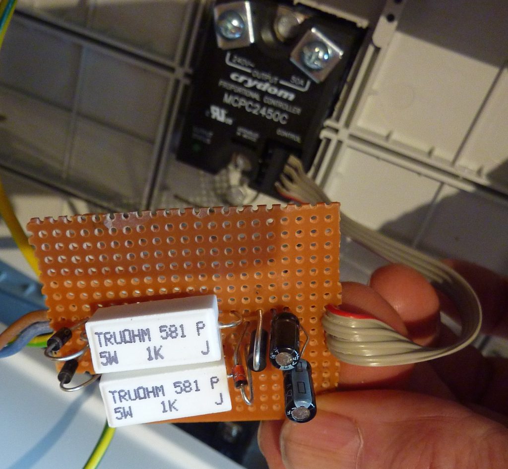
R1 and R2:- I suggest 1kohm 5W rated for 24V battery systems, and 2kR 10W for 48V battery. That way it runs cool. (For 12V or 24V you don’t strictly need R2 or D3.)
C1 and C2:- I recommend 22uF as this seems to be a good value. You need a capacitor to smooth the signal out, but a big cap results in time lag and ‘hunting’ of the heater current.
AC wiring
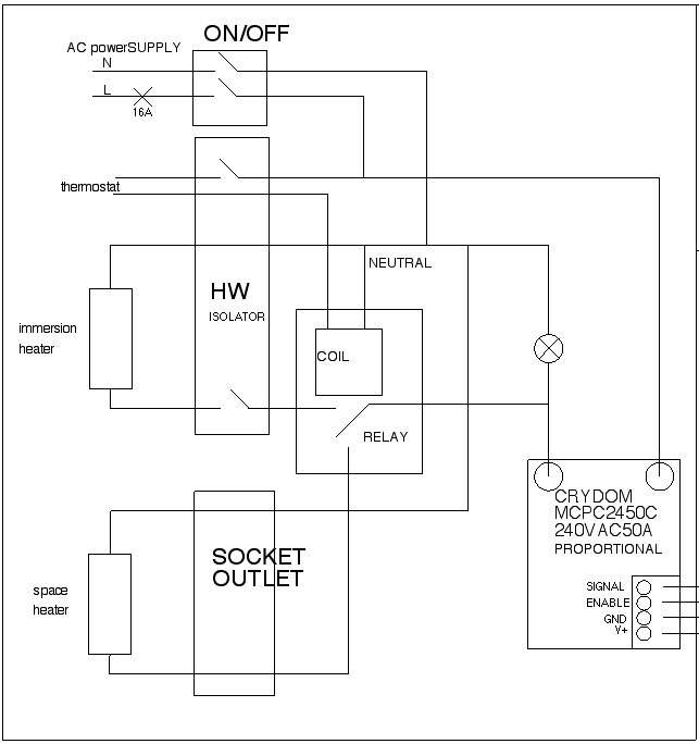 Take care when working with grid voltage AC from the inverter output! The SSR must be in a secure box. Everything metallic must be connected to earth ground. No connection must be possible between output and input.
The circuit on the right uses a thermostat to operate a changeover relay to power a space heater if the water gets hot. Or you can just use the thermostat to kill the water heater and fall back on your DC load resistance instead.
Actually this thing can run with a very small load (high ohm low watts) resistor provided that the AC load is always available, but I like to have a DC load resistor big enough to act as a fall back in case the inverter cuts out. A good DC load also improves stability and it actually uses very little heat when the AC load is there.
Note that the if the heater is open circuit (thermostat open for example) then the neon indicator shown in my diagram will light up due to a very small leakage through the SSR.
Heatsink
 The SSR needs to have a good heatsink as it will get hot and fail if you don’t look after it. I like to use a heatsink like this with the fins on the outside of a box and the SSR on the inside.
Up to 3 degC per watt is generally ok for loads up to about 3kW or 13 amps at 230 V.