
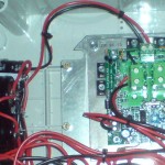
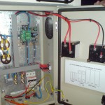
I’d like to give a bit of information about the LDR control boards that I get from Solar Converters and resell.  These are intended for battery charge control using a PWM diversion load control system, similar to the Tristar but without many of the features of the latter unit. My interest in them is that they can be used in ‘battery-free’ situations for controlling heaters and/or protecting grid-connect inverters. I have published an example circuit here. I have sold several units that are working well as protection for grid-connect inverters and on heating-only systems. This photo shows one inside a ‘Proven’ control box on a ’48-volt’ grid tied system at CAT in Wales (trouble free for two years).
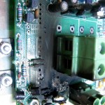
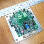
Here is a photograph of the LDR unit as supplied. It comes without a box, and the back-plate needs to be fixed to a suitable surface for heat-sinking (steel cabinet back-plate etc). The unit shown here is a ’96-15′ which is designed for charging a ’96-V’ battery, so its actual operating voltage is 112.8 volts. The ’48-30′ unit dumps power into its load at 56.4 volts and so on. These are the set points at which they would regulate the battery.
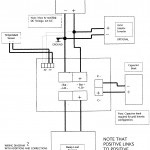
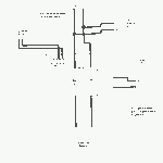
On the left are the nice big ‘battery terminals’ where you can connect a wind turbine rectifier. But first you need to connect the load resistance (suitably chosen) to the right hand terminals, and a bank of capacitors to the (top) capacitor terminals. Finally you will need to connect the ‘Battery’ input to the ‘sensing’ terminals at the bottom of the board as shown here. Also it’s important to earth the system negative.
If you make all of these connections correctly then the unit will work without self-destructing in seconds the first time the wind turbine speeds up. I have been operating a no-quibble warranty policy on these boards over the last couple of years, which has not been very profitable for me but I have learned most of the tricks. Solar Converters’ own manual (see scans in gallery below) as supplied with the LDR is not explicit, so if you want to have trouble-free operation you will need to take care to follow all the steps on this page.

HEATERS The heating load needs to be big enough to take all of the current the wind turbine will produce, which may be a bit more than you expect in gusty weather. (See also the need for a trip below in case of excessive current.) Here is a page about choosing resistance heaters.
Solar converters actually recommend that you use a low resistance heater which draws more current than the LDR is designed for, but when pressed for details they state that ” Short bursts of power over 30 amps can be handled by the LDR”. I do not recommend exposing the LDR to potential overload by following their advice to use lower resistances as the consequent damage cannot be covered by any warranty.
A heater that has too high resistance will not draw enough current and if you can’t consume all the current that the turbine produces then the voltage will rise and damage may ensue. If in doubt, use more LDR controllers in parallel, and/or include a safety trip.
THERMOSTATS are a tricky issue on such systems. Do not include a thermostat in the circuit feeding the heater. If the stat opens it will disconnect the load and the voltage will rise. You can use the stat cleverly to operate a pump that removes heat from the water tank and/or you can use another to trip the wind turbine into a stalled or braked state with a separate circuit, but do not use a thermostat wired in series with the heating load itself.
CAPACITORS. The unit is designed to work with a battery and in those circumstances it benefits from the stability of the battery voltage.  If there is no battery then it is essential to connect a bank of capacitors with a suitable voltage rating (I suggest about twice the operating voltage) and a large enough capacitance in microFarads. Connect more in parallel to increase capacitance. If you do not use capacitors then it will be destroyed the first time it tries to operate, as the wind turbine voltage will spike upwards when the load is turned off (briefly) by the controller (as part of its ‘pulse width modulation’ action, which is a rapid on/off cycle). The recommended value of capacitance is 20,000 microFarads, although 10,000 seems OK for the 96-15 unit. I use multiple 2,200 microFarad capacitors connected in parallel. Or for 48-V I would use these 4,700 uF caps.
Note that the diagram in the printed manual incorrectly shows several items connected ‘positive to negative’. Everything should be connected ‘positive to positive’, and ‘negative to negative’.

SENSING TERMINALS The sensing terminals are on a small connector in one corner of the board beside the temperature sensor. You must connect these to the ‘battery’ or the DC input. Otherwise the unit will not work and (in absence of a battery) the voltage will rise until it is quickly destroyed. These connections are not always shown in the diagram in the manual but they are described in the text and you must make them. Connect ‘bat+’ to ‘bat+’, and then ‘bat-‘ to ‘bat-‘ (parallel).
VARISTOR SUPPRESSOR AND EARTHING/GROUNDING Once you have all of the above connections right then the LDR unit can and will usually work nicely to divert power into the DC dump load, so that the voltage will not rise above the set point.  However there is another problem you could have if your system is not grounded on the negative of the battery or DC supply from rectifier. There is a varistor (wee blue blob) on the board close to the C+ terminal that will explode if the system is earthed/grounded to a different part than the negative. Please earth the negative. This is not compatible with earthing the neutral of the alternator in your wind turbine. If you earth the neutral then the varistor will probably explode (see right), and the unit will not usually work after that. (In the photo at the top of the page the damaged blue varistor has been replaced by a different one, but the unit did not work anyway.) If you earth both the neutral and the negative then the wind turbine will be shorted and will not turn. Connect the rectifier negative to the same earth/ground as the back plate of the LDR. Or if there is to be no earth (floating) then makes sure there really is no earth.
FUSES AND CIRCUIT BREAKERS are devices that protect against overload of wiring with excessive current. In most electrical circuits there is a source of power that is very large (mains grid or battery) that could potentially melt your wires and set fire to the building. In the absence of a gird connection or a battery there is only the wind turbine and the capacitors, both of which have limited ability to do harm. It is normal practice to short circuit the wind turbine for braking purposes and we do not wish to blow fuses or trip breakers when doing this. If the wires are large enough then you do not need a fuse.
It’s important to use wiring that is adequately sized to carry the maximum surge current your wind turbine can produce, to avoid overload. If you find it necessary to use a fuse or breaker then this should also be the largest capacity that you can for that wire size. A blown fuse will result in the turbine running away and producing excessive voltage which may be more dangerous than excessive current. A sudden interruption of the current to the load may well result in a voltage surge that damages the LDR controller too.
OVER-VOLTAGE TRIP I recommend you include some kind of over-voltage trip device in the system as a backup protection against having too much power coming in. This situation could arise for example in unusually windy weather when a gust causes the turbine to produce more power than usual for a few seconds. Or if the LDR controller fails to work it is helpful if the wind turbine trips off rather than producing excessive voltage which would damage the LDR and perhaps an inverter and becomes a hazard.
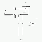
 This diagram shows a very simple trip arrangement where a relay is employed to detect voltage and connect an auxiliary heating load. The relay is adjusted using a variable resistance which can be a string of resistors as shown for minimum cost. The heaters could even be a set of three connected directly to the AC output of the relay in delta or star.
Another good option for heater control would be Schams MPPT controller for heating loads. Contact Schams for more info.

Hello Hugh,
I am currently planning to connect a 3m turbine with ferrite magnets to the grid. It was originally made for 24V battery charging.
I could probably get a used Windy Boy 1100LV inverter (http://ust.su/upload/iblock/99a/WB1100LV-IA-IEN104130.pdf) which is designed for low dc voltage input up to 60V. For some reason I can’t find a suitable “SMA Protection Box” that is working with such a low voltage.
And I could not find the LDR boards for selling and it seems that the solar converters website doesn’t exist anymore? Do you still recommend to use them and sell them these days?
I was wondering if I could use any diversion load controller and even the Tristar as a voltage protection for grid tied inverters? Should I always use capacitors or are they only important while working with those LDR boards?
all the best,
Ludwig
Hi Hugh, I wonder if you could advise, and. supply me with the correct dump load board as a replacement in my proven energy 6kw 240 volt grid control box.
The load is dumped through a 8 kw immersion heater.
I hope this makes sense.
Kind regards,
Graham Quarmby. Shetland.
Hi Graham,
It seems like you need a “protection box” for a windy boy inverter? I guess it must be something of that sort? SMA don’t make them any more.
It’s important to know the operating voltage. You’d need to be a bit more specific about that. Reading the labels on all the boxes and reporting what exactly you have got there.
I know a couple of good places to go for support with this. These are both helpful people with more experience than I of this sort of thing (grid connect turbine inverter protection).
Quentin at voltsys – maybe this product http://www.voltsys.com/home/index.php/power-one-20a-wind-interface/
Or Dave Wilcox at 2V microsystems http://www.powerpal.co.uk/ppelec.html [email protected]
Good luck. I am pretty sure these guys can help you better than I can.
If not then let me know 🙂
cheers
Hugh
hi Hugh Im trying to connect my gin long wind genr to a heating load ,but cannot find a suitable management circuit .The output voltage after rectification can be up to 450 v , output power exceeding 6 kw . Can you supply or suggest any circuit to manage a suitable load while optimizing genr. output. this operated formerly as a grid connected unit but I now wish to use it as stand alone.
hi John,
Not many people find it worth while to run a wind turbine just for heating so there are not may controllers our there. I know that Schams Electronic in Germany are developing one just now though. It’s not on the web site listing but it’s a product under development and one to watch.
One solution that I find works nicely as a substitute for MPPT is a judicious combination of a series heater and a PWM-driven voltage regulator heater. For example you might choose to use the LDR-96-15 which starts to divert power into a load resistor at 112.8V. I can’t say if this is a good cut in voltage for the Ginlong turbine as I do not know them in detail but it might well be. Use a diversion load to suit the 15 amp rating of the controller, say 7.5 ohms 1700W or higher rating. Also put a similar resistor in series with the LDR (between it and the wind input). The result is that the voltage will rise with current. At 15 amps you will have 225 volts or so which may be ideal for generating 3-4kW of power. IN your case you might want to use two of these setups in parallel to make sure it can handle the 6kW output.
I hope this helps.
Hugh
Dear Sir,
Thank you for your information on the LDR load control, as you always been given people some diagrams about control circuit cannily advice me about my problem of controlling the wind turbine to have stable voltage to pump water with Grundfos pumps helical or centrifugal pump motors that can used wind turbine with 120v DC and 180vDC 1000watt 10ft diameter, the pump is 60Hz 3/4Hp . How to build wind turbine 120v and 180v DC with 1000w, rotor 10ft. Please give me the data turns per coil, how many coil, AWG and magnets size. the control circuit to control over voltage. Thanks, God bless. T. L. Odumosu.
Hugh
long time not interface. hope you are good. Niall has been doing great things here rejigging and figuring the 3.6 and the 2.4 blades of your Sep 2007 course.
Thankyou for delivering the LDRs through Jimmy and Miriam. How much do I owe you for them? Do you want to send me bank details or let me know your ideal payment method.
Hope we can do another course here before too long – have notions of the 4.2 on the second mast. Perhaps Niall mentioned it.
all the best and hope Scoraig is all good
Colum