You can get in touch with me by email using [email protected]

Digital image
The best phone number is my mobile +44 77 1315 7600. This is also Whatsapp and it’s often the best medium to easily share pictures and videos as well as voice chats or messages.
I tend to forget stuff people tell me on the phones so I do recommend putting it in writing in an email or Whatsapp message.
Postal address:
Scoraig Wind Electric
Dundonnell
Ross shire
IV23 2RE
Access for visiting see this web link. It’s best to contact me in advance if you want to visit.
Hi,
I just wanted to reach out and let you know that your content has been quite helpful for me.
My friends from Allthingsaustria recommended your site and I’ve not been disappointed at all 🙂
Cheers,
Mihkael Caron
Hello and congrats,
did anyone evaluate CVT (Variomatic): https://en.wikipedia.org/wiki/Variomatic
as gearing system for wind turbine?
Hi Gabriele,
Efficiency 75% is not a good sign. Also the turbine does a lot of hours, so I suppose it will wear out.
Short answer is no, I have not heard of it but my advice is keep it simple.
cheers
Hugh
Thanks Hugh.
Hi Mr.Hugh
Today i decided to move to another house leaving the crowded noisy city at last
and i’m going to build the 4200 turbine using enameled aluminium wire for stator windings instead of copper (cost issues)
I’m building the 12v version but 100 turns of that thick wire will make the winding core heat up to a dangerous temperature (I assume)
(I may increase wire thickness as aluminum has higher resistance than copper)
If so, is there any way to use aluminum safely?
like attaching fins to rotor to act as a cooling fan, or attaching heat sinks with thermal grease to the outer walls of the coils
or i won’t even need to cool it down and it will work just fine as i’m gonna shade the generator from the sun and mount the turbine at higher altitude
regards
Shams
hi shams,
I am sorry but you can’t use aluminium wire for this. It has too high resistance. If you do that you will need to modify the tail to reduce the output power. It’s really not a great idea. The money you save is not worth the loss of performance and the likelihood of failure.
cheers
Hugh
so be it .. I will use copper
but after i roughly calculated the new house consumption (didn’t measure yet), I found out that I need about 500 kWh monthly which is nearly the maximum production of the 4200 turbine
So I may need to scale it to 4500 or 4800, should i increase stator coils windings to 120 turns or increase thickness to 1.8 mm or what would u advice me to do ?
regards
Shams
Nice website!
I saw your diagram that shows … The current *ONLY* flows between the most positive (+) phase and the most negative (-) phase. This can be true, but only when the Voltage between two of the 3 phases is less than the Battery Voltage. Therefore, I think there is a period of time where the current is SHARED between the two negative (-) phases or the two positive (+) phases. I say this because the Open Circuit Voltage of a coil will rise. If Phase A is at peak positive (+) then the current will be slowly transitioning from (-) Phase B (decreasing amps) into (-) Phase C (increasing amps), until the voltage across ( Phase A + Phase B ) is LESS THAN the battery voltage … then, and only then, will the current in Phase B rapidly drop to zero amps. Since the Open Circuit Voltage of both Phase B and Phase C are clamped down to the SAME battery voltage, BOTH (-) Phase B and (-) Phase C can carry a percentage of the return current from (+) Phase A. Have you looked at the waveform of the amps per phase on an oscilloscope? Is there any time where the return current from (+) Phase A flows back through both (-) Phase B and (-) Phase C ?
Catching up with old comments I had not seen before. Yes you are right that there is some sharing due to internal impedance in the phases so my analysis is oversimplified. There have been some more sophisticated analyses done but the result is not dramatically different. DC transmission at the peak voltage is always going to beat
AC for efficiency.
Hello i want to make pmg generator 200rpm max 1kw 12v can you helped me for pmg desin? THANKS
hi Ghulam,
Yes you can use the alternator in my Recipe book for the 4200 model (4.2m diameter blade rotor). Use 16 magnets on each disk (450mm diameter disks) and use 100 turns per coil connected in parallel. It is all described pages 35-48 in my recipe book.
cheers
Hugh
Hi Hugh. Arthur Sheridan here. Do you know of any solar tracker plans? There was a French homestead that built two of your 3.6m wind turbines used to advertise plans but I can’t remember the site. hope to hear from you soon. Arthur.
I think you are looking for a chap called [email protected]. He has published some plans for a PV trackert and is in Normandy
https://www.bookdepository.com/How-Make-Low-Cost-Simple-Robust-1-5kW-or-2kW-Double-Axis-PV-Solar-Tracker-Leslie-Ronald-Arthur-Bryan/9780993590313
Here is the book he published
Hello Hugh,
I am working on a 2F Piggott wind turbine and now I want to test how my electronics work. I have connected everything as you recommend. I have a Tristar TS-45 charge controller running in Diversion Mode. My 2F Piggott is a 24V system.
My question is: Is it a complete connection scheme with all components on your website? What confuses me is that I have to connect my wind turbine (via rectifier) directly to the battery (Tristar controller and inverter too) and the wind turbine produces variable voltage: from 0 to maximum voltage but the batteries have to be charged with 24V nominal(2x 12V). So is Tristar somehow able to control this kind of charging process, when the wind turbine produces variable voltage (even if Tristar is connected parallel to wind turbine charging battery)?
When my wind turbine charges the battery, the battery works as a load. So does Tristar vary this “load”? As I understand you have to have less load when the wind turbine is running at low wind speed and more load at high wind speed. Won’t it be too much load by a battery at low wind speed?
Thank you!
Jurijs
Hi Jurijs,
The voltage of the wind turbine is highly volatile like all permanent magnet alternators operating at variable speed. When unloaded the voltage rises due to increasing speed and the lack of internal volt-drop. You then see the “open circuit voltage”. When on load the voltage falls. When short circuited the voltage is zero, and a high current brakes the turbine with high torque.
In a battery-connected situation, the voltage must reach higher than battery voltage before charging starts. During this time the blades overspeed slightly as there is no load on them. When battery voltage is reached, a current begins to charge the battery and this does two things. It restricts the speed of the turbine (creates a torque slowing the blades) and it also reduces its voltage (due to internal loss of voltage from current and resistance). The operating voltage is largely controlled by the battery as the turbine would need to deliver a very high current to make a difference to that. The battery voltage gradually rises as charging progresses. When the optimum charging voltage is reached, the Tristar starts to divert surplus current to the dump load so as to maintain that ideal voltage level if possible. If there is not enough wind then this is target often not even possible. But the controller ensures that the battery voltage does not rise above it. So the battery gets what it can and is never damaged by excessive charge.
Do not place a controller between the turbine and the battery. The turbine must charge the battery with all of its current. Any excess current beyond what is needed will be diverted by the Tristar.
Ideally the voltage of the load on a turbine would increase directly with windspeed. That way the blades would run at their optimum speed in any wind. In the battery connected situation, with low winds they cannot run fast enough and they need to overspeed a little to charge the battery. In higher winds the battery voltage is a little lower than the best voltage and this restricts the blades’ speed which again impacts on the efficiency a little bit. But the whole thing is carefully designed to harvest energy well in the most common wind speeds and work as best it can without needing expensive and possibly unreliable MPPT controllers.
I hope this helps
Hugh
Buen dia donde puedo comprar el manual de construccion de aerogeneradores en español?
http://www.500rpm.org/
Thanks again Hugh!
The PV Plant install is tentatively “planned” for late winter / spring timing. I won’t consider a HAWT until it is in and producing power.
The blade diameter is larger (twice!) what I was thinking — so I may need to reconsider if I am serious about supplementing the PV with a HAWT. ROI is an important factor to consider.
Thanks again for your sage counsel and input.
Hi Hugh.
I am an RV enthusiast that lives in it full time. It is an “all electric” model which means essentially that I do not have LPG for heating and cooking – but instead use an electric (and diesel when it’s rally cold) powered “AquaHot” system for heat / water and an induction cook top for, well, cooking.
I am planning to install a PV system with Lipo / LiFe batteries this summer so we an effectively live “off grid” (campgrounds become unnecessary). I have not decided on the size of the PV plant and batteries as I need to capture my consumption over time in order to equitably analyze the data to properly size my system.
My question: Is it possible to install and operate a HAWT that I could put-up/take-down as needed (not too heavy and something that will disassemble into several stowable pieces) to scavenge electricity from a wind source (up to ~24 hours vs sun of ~10 hours). If it “is” possible, what do you consider to the the minimum height above ground (this may ultimately depend on the location of “other” structures.
Is there a “brand / model that you could suggest that would be RV friendly? It would have to be easily taken apart for stowage between stops.
hi
to be honest this is not an ideal situation for wind power. Your camping places are likely to be sheltered locations. wind turbines need to be placed as high as possible in strong, steady winds. Solar is more likely to work for you.
I wonder if you have done you sums about how much solar and wind you will need to do the various things you plan such as cooking and heating though. It may turn out to be somewhat unwieldy.
Renewable energy is more suited to being permanently installed in suitable locations than used on the road (in my opinion).
cheers
Hugh
Hi Hugh.
Thanks for the quick response.
I agree that the RV location will have a substantial impact on the viability of the HAWT to produce usable energy – and sheltered locations (i.e. trees & buildings) will create an even larger challenge — if not render it ineffective in that location.
I was thinking of the wind turbine only as a supplement (an alternative energy source in addition to the PV plant that I plan to install) and as a way to harvest the wind(s) both during the day – and night (while the PV plant is dormant but the pull from the batteries are still present).
The application may not be ‘ideal’, however, I was hoping for a recommendation of the HAWT unit that might be small enough, yet be able to produce an effective amount of energy to make its implementation worthwhile.
Current thinking is that my daily draw will be 500~600 Ah thusly requiring a battery bank of ~800 Ah and a solar array of 1000~1200 watts.
If this is a “fools errand” then I will stop thinking about how to deploy a HAWT in my intended application, however, if the application has merit…….
Hi
You are going to need 6 or 8 solar panels to do that. They will need to be well placed. The wind turbine could contribute if you happen to be in a windy place on a windy day but unless it is is 6-8 feet or so in diameter the contribution will not be decisive.
cheers
Hugh
You should consider making your green energy system on a small trailer flat bed or enclosed and tow it behind your RV like i do. I have 1200 watt array on my trailer with single axis tracking and a stationary 600 watt suitcase array i can plug in and setup.i.also have a prototype wind turbine tower and it can fold down and is telescoping for hieght 14ft 30ft 40ft 60ft ot depends on what length tubes i put on my tower
I also can put 12 6v batteries on the trailer. I used an old free truck bed tool box for battery box and made custom copper bus for power in and a bus for power out or inverters. I have a 50 amp hardwired port and a 30 amp port my bank is 1410 ah 12v. Someday i will make it 48v or 60v but for now its 12v. The bank requires a good charger that can charge it with a generator or shore power. 140 amps 14.8v is a good charge rate for a big bank like mine. I used 4/0awg cables for 6 ft power out bus and 4ft for power in bus. I also installed several temprature controlled relay boards and blower fans for my cooling system and i have dc led lights that turn on and off at day and night. I have 6 battery desulphinators to keep my plates clean and a 100 amp rectifier and dump control board and sooid state relay and 300 watt 3 ohm resister bank for my 500 watt 3 phase ac turbine. Check it out hope this gives you a good idea how to camp offgrid like i do. My system can power 5 RV campers with out ac units running or 2 RV with AC running. I also have an ATS IN MY HOUSE so i can power some stuff at home with the unit too. Here is the video i have several im always updating. https://youtu.be/CVyjtJY2h6E
Update for you. Grid tie inverter connected and synchronised 1st time with output showing 150 watts at 170V. Next off to programme in the power curve you supplied. Now it is getting exciting.
Thanks.
Andy
Hi Hugh, just wanted to let you know that the new 4.5mtr turbine is now up in place. We winched her up first thing this morning and the hinged tower dropped perfectly on to the studs in the base. I’ve still got some relays to connect up but with a 4mtr wind I let the brake of and soon the invertor was recording power in; and also showing failure to synchronise. Quite correct as I have the AC output breakers out at present. So not actually putting power into my home mini grid but still feels very good.
I’d like to thank you for patiently answering my questions as the build has progressed and your help and encouragement.
I’ll let you now how the power curve works out when I get the Aurora programmed.
Thanks again.
Andy
Dear Mr. Piggott,
we built our 2F Piggott wind turbine with PureSelfMade Workshop 2 years ago. Now we want to install it properly but we don’t know what to do with the cables, which are coming from the generator. If our wind turbine rotates a couple of times around the vertical axis because of the wind the cables will be twisted. The cables come from the generator directly to the electronics and there is nothing between them. Is there any solution?
Thank you
Jurijs
hi Jurijs,
I normally install the turbine with tough, flexible single wires hanging inside the tower pipe. Use equipment wire such as “tri-rated flex” that will not be damaged easily. Make it longer than you think it needs to be. It can twist several hundred times without problems. Every year, or when you think it needs it, you can disconnect the wires, put them together to brake the turbine, put them into your cordless drill and unwind all the twists using the drill. Put a few twists into the wires in the other direction while you are there.
On some sites the wires twist up rapidly due to gusty turbulent conditions. On others they do not need any attention for years.
cheers
Hugh
Hugh, thank you for your answer!
Jurijs
Hello Mr. Piggott,
I am a senior at Rutgers University and I am working on building an airborne wind energy system for my senior design project. We are essentially building a balloon/kite hybrid structure and attaching a wind turbine to it. We are aiming to have the structure fly at about 30m in the air which would result in winds of 10 m/s at where I am located. Our design has a power cable acting as a tether for our balloon so the current must run through 30m. We must account for a voltage drop. The main objective is to charge a 12v battery placed on the ground. Our blade diameter will be approximately 51cm. I am having issues on deciding what motor to use as my generator. I have been receiving help from our sponsor General Dynamics on our choice and they recommended us that we use a 24 V DC permanent magnet motor. Unlike other wind turbines, our wind turbine needs to be lightweight and our blade diameter is significantly smaller. I am having issues on choosing the correct amp rating and rated RPM, torque etc. If you could give me some insight on choosing the correct motor, the help would be greatly appreciated.
hi,
The basic equations are as follows:
Power = 1/2 x density of air x conversion coefficient x swept area x windspeed cubed
= 1/2 x 1.2 x 0.25 x pi x diameter squared/4 x 1000
This comes out as about 30W for 0.5m and 10 m/s wind and 25% conversion efficiency (power coefficient).
RPM is tip speed divided by circumference, times 60 seconds in a minute.
If tip speed ratio is 5 and wind is 10 and diameter is 0.5, then
RPM = 50 / (pi x diameter) x 60 = 1900 rpm approximately.
When looking at motors, bear in mind that the open circuit voltage varies directly with RPM, but operating voltage is lower due to internal impedance.
I hope this helps. You will need to maximise your tip speed ratio to maximise RPM and reduce the weight of the motor. But starting torque is a serious challenge with such tiny blades.
cheers
Hugh
Hello ,
I’m Studying 3rd Year Mechanical engineering in IT Sligo and we are doing a Vertical axis wind turbine as part of our final year project.we are in the middle of building a generator and a helical blade for the turbine but we are having difficulty in producing the blade using airfoil, what type of blade would you recommend to use in the Irish climate, also we have diff users on the turbine which automatically adjust as the wind speed gets higher.
Thanks
Hi Zorar,
I am very sorry to tell you that I do not recommend vertical axis nor diffuser augmentation. I cannot suggest a good blade profile. I know that these ideas are popular in universities and much time has been wasted in refining the designs but it’s a dead end. If it were ever going to provide useful results then this would have happened a very long time ago. I don’t expect you to change your approach but I just need to give an honest explanation for why I cannot help you.
cheers
Hugh
Dear Hugh,
As a complete novice to wind turbine building, but having the motivation to move forward after reading “Windpower Workshop”. I have a fairly basic question to ask regarding “Airgap”
I have selected a very small plug in fan as the basic object to convert to become a turbine/generator. The rotor is 44mm diameter and the stator is close to being 45mm diameter. Obviously the existing air gap is very small but I am thinking to ask,” If I machine the rotor down to a smaller diameter, eg 35 mm and milled slots to accept the ferrite magnets, what of the airgap? Is it measured from the upper surface of the magnets or from the surface of the reduced diameter rotor.”? or is this question completely irrelevant to my proposed alteration to the very small object that I have in front of me. The stator has 16 coil windings, each 13 mm long across the laminated steel core. The magnets that I have are 4.1mm thick by 6mm wide, 100mm long.I propose to cut these with an angle grinder mounted slitting disc to fit the slots in the rotor. Am I wasting my time, it is only an experiment and I am not seeking to generate high voltage only a steady small voltage “trickle”?
I am really inspired by your book and this motivates me to ask. Please advise if you have the time.
Sincerely, Stephen .
hi Stephen,
My immediate reaction is that you have chosen a very unsuitable starting point which is going to make the task very difficult and the results if any will be miniscule. I am sorry to be so rude but it’s probably best to be honest.
The problems with building/converting a generator that is suitable for wind power is that the rpm must be very low and the parasitic losses also low. This is a high rpm motor that you can convert to work at low rpm but only with very low power output and very low efficiency. The key things to look for when choosing a motor for this job are large diameter and low magnetic losses. It’s simply not possible to fit enough magnets and copper into that size machine to produce power at low rpm and the laminated core will work against you if you try to build a very low power machine.
If you sink magnets into a steel rotor then you create leakage pathways for flux at the sides of the magnets that will rob much of the flux the magnets should be sending through your coils. Cutting magnets is difficult, and if you cut NdFeB magnets you break the protective coating and they will degrade fast. Again this is a bad way to start the job. BY all means use what you can find, but do search a bit further before you set yourself up with monumental challenges that are not even necessary.
Given that permanent magnet motors are common nowadays, why not choose one of them if you want to use a motor. Or if you want to build an alternator then do not even start with a radial flux motor body, but go for the axial flux type with no steel cores in the coils as described in my Recipes and the 2F design.
YOUr question about air gap is a good one. The air gap is the axial length of gap in the magnetic circuit that is not a steel pathway. This means that the magnet itself represents part of the total air gap (although this is not usually recognised). This is rather analogous to the concept of internal resistance in the electrical circuit. Remanent flux Br is the flux you get when there is no air gap other than the magnet’s own length (which cannot be avoided). Any additional gap will reduce the flux. If the air gap is equal to the magnet length then flux density tends to be half of the Br. This is a good operating point (around there anyway) for an axial flux machine with no steel core, but machines with cores generally have much smaller gaps. I dislike cores because although they allow you to get more flux with less magnets, they also create high reactive impedance and/or “armature reaction” which may or may not be the same thing. Whatever this effectively limits your output current. Cores also suffer from parasitic losses and cogging torque.
I hope this helps. Ii am sorry not to be more positive about your choice of motor.
cheers
Hugh
Hello Mr. Hugh ,
I know you’re not a big fan of VAWT but i just decided to build one with gears since i did watch someone’s video who did it before and it worked generating about 1 KW ,and my desired output is about 1.5 : 2 KW but i have 2 ideas to do some modifications to lower the RPM and i wanted to ask first before i import the magnets
1- Using N42 NdFeB Arc Segment Magnet Diameter 60mm OD60xID10x45DEGx5mm instead of the normal N35 shape since it will be covering the whole coil , but i think there will be a need to modify the shape of the coils and it’s turns.
2- Doubling the stator by dividing the turns of the coils and set the 1st stator as normal shape and the other one above setting and directed to the spaced areas of the other one , so when the magnets turn the flux would cover the coil and with a little turn will cover the other coil of the other stator in my opinion which will lower the RPM .
by the way i’m not expert but i like to make my own turbine and i did read alot from your book and your replies to the others
Thank’s and best wishes .
hi Abanoub,
To help you with alternator design I need to know the rpm, voltage, number of magnets, proposed disk diameter and all other details you can think of briefly listed.
cheers
Hugh
Thank’s for your kind reply
well , all the details you have asked about will be the same of your explained 1 KW PMG in your book and the desired rpm would be 100:120 and voltage is 24V , the number of magnets will be 12 pieces on each plate and the number of coils are 10 , 100 turns of 1 mm per coil for each stator
but i still can’t decide which shape of magnets i would use to be able to answer your point of the disk diameter.
also as i have informed you before i’m not expert with calculations so i would be glad knowing the right thing from you since i can’t find any source to read about this here in egypt
Thank’s and best regards.
hi
I am sorry but I do not have a book about making a 1kW PMG with ten coils.
It will not be possible to generate 1kW power at 120 rpm using 12 magnets of this size on each disk. It’s too small.
cheers
Hugh
Hi Hugh
I built the wind turbine 2400 diameter 24v which turns with the tristar ts 45 on two battery 12v 110ah, I would add in addition to the charge of the solar panel battery to make a hybrid installation, can you advise me for the choice of material, power and for conexion.
thank you.
laurent.
oops I forgot there is a discharge resistance of 1ohms 1000 watts for the derivation
Hi Hugh,
are you having trouble with the internet and email again. Or perhaps your simply soaking up the summer sun!!
Hi
I have been away from home.
cheers
Hugh
Dear Sir Hugh,
Greetings from Philippines!
Sir do you have a recipe for a 10KW alternator on your ebook? I am planning to build one myself if I have a guide about how to make one in detail.
Sincerely,
Jess Juliano
hi Juliano,
Sorry no, I do not publish plans for a 10kW alternator but if you tell me the rpm and voltage and suchlike details then I can design one for you.
cheers
Hugh
Hi Hugh,
I built a 40 magnet by 30 coil PMA and am finding that in low winds the Alternator does not turn.
I was wonder what you think of the following:
That I wire up 7 coils coils (equally spaced around the coil circle as best I can) to switch 1 and then do the same for switch 2 and for switch 3 and switch 4 controls the remaining 9 coils.
This way when there are low winds only switch 1 is engaged and as the wind increases more switches would be engaged.
Also, would this arrangement need 4 rectifiers and could these be fed to a single inverter?
If you have covered this arrangement/issue please just point me to it.
Thank you.
Hi Hugh,
Just wondered if you’d come across this “chocolate teapot device. Some body posted this link on Navitron, thought you’d like it.
https://facebook.com/EVChargeUK/photos/a.1889162704688321.1073741830.1846457885625470/1889201028017822/?type=3&fs=1
http://www.elquatoruk.com/
Mind boggling.
Andy
Thanks Andy,
It’s lovely. I hope they make a lot of money and a lot of people happy. Until they find out it doesn’t quite work? But who cares – it’s ecofriendly. Or something…
Hugh
hello Hugh,
Thank you for the quick reply.
I use neodymium magnet for the 2400 in 24 volts size 50x22x10 grade N52. This magnet size and it’s good compared to the magnet you used?
Thank you.
Lawrence.
hi Laurent,
OK it’s confusing for me too now you tell me this, and I think you should use 50 turns. Maybe the coils will need to be a little thicker than normal, but the grade 52 magnets will be able to deal with that.
cheers
Hugh
hello sir piggott.
First of all I want to congratulate you for all your work.
I have a question about the wind turbine of diameter 2400.
The wire diameter for the coil in 24 volts and 2×1.5 in 45 turns or 2×1.5 in 50 turns? it’s a bit confusing for me.
Thank you for everything you do.
cordially.
hi
You need to make 45 turns per coil using 2 wires in hand, each wire being 1.5mm in diameter.
have fun
Hugh
Hi Hugh,
sorry for the late reply.
I was hoping to build a turbine that can produce around 48v, around 580 Watts.
would that be enough to charge a set of 12A batteries.
As I mentioned I’m using the 6 coils 8 magnets design but I’m using double head rotors. so 16 magnets.
hi Mohammed,
Yes you can use my standard 48V alternator for the 3000 option in the recipe book (3m diameter wind turbine) with 110 turns per coil. If it runs too slowly you can increase the air gap to tune the turbine RPM.
cheers
Hugh
Hi Hugh,
I’m a Mechanical Engineering student. I’m designing a micro-hydro power generator.
I’ve looked at your (Wind turbine workshop) book and it helped me alot in my research.
I have a few questions.
I’ve designed my rotor to have 8 magnets (as shown in the book).
How many coils, windings per coil I could use to get a desired voltage of 48v?
is there an alternitave desing of stator/rotor that you recommend?
I have a head of 26m, and an approximate pressure of 3bar, and roughly 350RPM.
Kind regards,
Mohammed
hi Mohammed,
It’s quite likely that you can use one of the recipe designs for your turbine. Other have done this. to help you I need to also know the power of the turbine.
cheers
Hugh
Hello, I’m starting a camper’s build, and I have just bought your 2F book.
Is it feasible for an rv vehicle? What are the “folded” dimensions in order to store it attached to the rear?
It is a 7.5 meters minibus, and my idea is to weld a telescopic mast to the rear.
Do you know of any discuss about the subject? (maybe it is not possible at all or not worth it)
Thank you very much and best regards
Manu
hi manu,
This can be a lot of fun, but not the most practical way to make power compared with solar PV. You need to use a tall tower to get above obstructions (trees and buildings) or you need to park on a hilltop. Then there is the noise and vibration inside the caravan when it is working well. It will sing you to sleep! You have to love it to live with it, I’d say.
I have seen people make folding towers that bolt onto their trucks. Yes you can pack away the turbine. The blades are pretty big though and it takes a while to dismantle them. Can you store it on the roof maybe? Take care that water does not run into the bearings. this can happen if the machine is stored face down and the rain runs in the back.
Have fun!
Hugh
Thanksvfor the quick reply.
I’m just studiyng the project, nothing fixed yet.
I don’t look forward big harvest, just to help in winters.
Best regards
I forgot to mention that it is 3.4 meters high.
First I want to introduce myself, my name is Joost.
I am qurrently working on this big project that has things to do with generating
electric energy.
So my question is if you would like to help me with making this project into
reality, it would really mean a lot to me, I’ve contacted a lot of people but
they’re not as excited about it as I am. Once again I would really appreciate it
if you helped me even with the smallest things.
I hope that i asked the question clear enough, and I would like to receive a
reply if you are interested.
With kind regarts,
Joost van der Wal
hi Joost,
I am sorry but you have not asked me a question yet so I cannot answer. I would like to help everybody but first they have to ask a question.
cheers
Hugh
Hi Hugh,
I have been a fan of your turbines for years and wanted to make one.
I started by making your 1.2 meter blades from (how to build a wind turbine) which I am very happy with, but now have your (recipe book) which has the interesting 1200mm design.
Can I use the original (how to build a wind turbine) 1.2 meter blades, on the (recipe book) 1200 alternator? Is there a different T.S.R between the 2 blade designs? Would I have to change the number of winding to the coils?
Many thanks,
Ian
hi Ian,
those blades will work fine on the Recipe Book Alternator.
Have fun
Hugh
Hi Sir, I’m a Aeronautical Engineering B.Sc. student at Polytechnic of Bandung, Indonesia, My final assingment is about blade pitch control for low speed wind turbine, but i’m confuse in mechanism of it, do you have any reference or image about it? i’ll be very greatful. Thanks
Hi Hugh, it’s been about forty years since we last spoke. We worked at a sheltered community in South Wales for a winter and then I came up to visit Scoraig a couple of times over the next few years. I only met Topher the one time.
In my mid twenties I moved to Southern California and have pretty much been here since. I worked as a Physiotherapist in hospitals for the last twenty years. I thought about Scoraig from time to time . I was amazed when I finally looked it up on the internet and saw a u tube video with you in it! Especially ironic as I’m moving towards solar power as a fine off grid solution here in the land of sunshine. I live in the mojave desert not so far from awful LA. So cheers and hello from the dim and distant past. I was just in Liverpool visiting my old mum. Ha ha
04/09/2017 at 09:20
Good morning Hugh,
Thank you for the previous information we requested. We have since ordered 1.6mm wire to make the stator.
We now have another query, we have more or less finished the three blades. Can you see any problem with epoxy glass coating them? We are certainly au fait with the technology having previously built several yachts and dinghies with ply and epoxy glass coatings. We live in an environment of extremes in Crete and have fluctuating temperatures of minus 2 to 40c in the Summer. We also suffer from damp salty air and we are only 5km from the sea. Wind speed from nothing to Beaufort 9! When we have extreme wind from the south, we often get Sahara sand in the air also.
Many thanks.
hi Nick,
It’s tricky to follow our conversation as it jumps around different posts but I have tracked it down.
If you know what you are doing with epoxy and glass finish and can make a neat job then that should be fine. I am a bit wary of epoxy paint since a bad experience a few years back. This was a commercially made machine with wooden blades and epoxy paint coating. Water entered the blades where they were drilled at the roots (for bolting to the hub). This water centrifuged out to the tips and caused them to swell and finally burst, which was pretty messy. I believe that normal paint would have allowed the moisture to escape more gradually.
I mostly use linseed oil instead of paint. It takes a while to dry but it lasts well and protects the wood. Maybe not so well in your climate with all the sun.
I build the leading edges up with epoxy when repairing erosion damage and this lasts much longer than the original wood. The leading edges near to the tip get eaten away by wind erosion. You can remove some wood at the outset and rebuild with epoxy paste but I normally wait until the first service and do it then.
cheers
Hugh
Hi Hugh,
Sorry, figure of speech!…I, ‘plugged in’ the numbers to the equations! :-), anyway, you were correct, on looking at my numbers again, I was using the efficiency factors incorrectly.
I had calculated the power from the blades and generator in two separate calculations, so not really dependent on each other as your book procedure shows. This, I think, is my mistake.
I calculated the power in the blades (275W) based on the Betz equation and an 11 m/s wind this, I had forgotten, also had a generator efficiency factor included, so it was already giving me a ‘net’ power output using an assumed generator efficiency.
I then calculated the generator total power losses (285W) based on the procedure in your book and compared the two values. Ofcourse when I remove the generator efficiency factor from the blade equation the ‘gross’ blade power output required goes up to about 485W, which while not giving me a good design (41% overall eff. for a 200W output), makes a bit more sense.
Cheers Peter
Hi,
Is there a frequently asked questions page on your site Hugh as this question has probably already been answered?
…….I’m curious to know if the Cp (.35) your wind power recipe book quotes is realistic to attain. I am guessing this comes from your own measurements over the years so shouldn’t be doubting it I know, however a number of articles I have read indicate a Cp of around .15-.16 is probably more realistic? I’m currently doing the calcs for a 1.6m diameter 24v/200W design.
hi Pete,
0.15 would be a likely figure for a crude design of homebrew turbine such as I would have done before I got my hands on permanent magnets, or such as a vertical axis job or whatever. Nowadays I think it’s closer to 0.25. Blades might be at 0.35 but the alternator efficiency and rectifier and cable losses and stuff knock that down a bit.
There’s a page about performance measurements and you can find a lot of data there to check for yourself.
cheers
Hugh
Hi Hugh,
OK thanks for your advice. I shall check out the measurement page you indicated.
I was flip-flopping between .15 and .35 while experimenting with the numbers and did run some calcs using .25 to see what effect it had, I also included in the calcs separate factors for any transmission and generator efficiency; so it kind of seems as if I could actually use your .35 for the blade power alone and put in 1.0 for the transmission (as it has no gears or belts) and a generator factor of .85 or so.
Once again thanks for your response,
Cheers Peter
hi
In my designs the focus is on low wind performance, so the permanent magnet alternators are very efficient in low winds but the efficiency falls quite a bit toward peak power output. This is because the losses are all due to current in the wires whose heating effect rises with the square of current. So although .85 is ok for low winds it is probably nearer to .6 in at full power. Add to that the rectifier losses (around 10% for 12 volts systems, but less at higher battery voltages) and you get a less rosy picture. But as I pointed out, my priority is low wind performance (combined with reliability and ease of building/maintaining).
I have been checking overall efficiency (of the recipe turbines) in terms of energy produced compared to the theoretical maximum energy over the year, and find that 20% is a typical figure. This is not peak efficiency but averaged out, based on energy produced. Much is lost in high winds due to not having the alternator capacity to use it, but that is good because it makes more sense to have large blades than a large alternator given the choice.
Incidentally I find that commercial wind turbines (Britwind, Bergey) are closer to 30% in independent tests. They typically have higher power alternators to cash in on higher winds.
cheers
Hugh
Hi Hugh, I plugged in the Cp.35 and .6 for the generator efficiency and using a standard wind speed of 11 m/s the blades are producing about 275W and the losses in the coils and miscellaneous losses amount to 285!… so I have a very good electric heater at full power!:) ……..I think I’m gonna need some bigger blades!
hi Pete,
What did you plug it into?
I am not sure you are using the efficiency factors properly. If your blades produce 275 watts of mechanical power and the alternator is 60% efficient then you will get 0.6 x 275 = 165 watts electrical output and you will lose 110 watts to heat in the process. Not 285 watts. Yes bigger blades are always good if only because they will produce something usable in low winds. When the wind gets stronger the main issue is not so much efficiency as survival. Windpower is about feast and famine.
cheers
Hugh
G’day Hugh!
Thanks for getting back to me on this brain teaser!
So… Without building a turbine we won’t know the exact RPM and TSR; are you suggesting we need to build a turbine first to then design an alternator around these values? What I wonder is how these figures would change again once connected to the generator?
I spoke to somebody on fieldlines who has made a VAWT which produces 14V at 60RPM and has a maximum 200 RPM. I think we’ll be working in similar parameters. He suggested using a single phase system.
We’re definitely not trying to go the hard way round! Each turbine will be directly supporting one bulb (i.e. not charging a battery) which is why we thought a VAWT would be suitable for the job. A HAWT seems to be much more heavy duty, charging batteries etc. Initially we were hoping to see a fluxing in brightness by using an incandescent 40 or 60 W bulb, but if this is proving difficult to achieve then an LED with a much lower wattage would do the job instead!
Thanks again for you time!
Hi
Yes you can use trial and error. In reality the power will be highest at a particular rpm in relation to the windspeed. This is the optimum tip speed ratio. Free running will be faster, maybe twice that rpm speed.
I only suggest following my plans because they will work better than a vawt, and are all set out so you do not have to use guesswork. they come in all sizes. You do not need to use a battery.
Incandescent bulbs will probably be a better idea than LEDs for variable voltage operation so long as it does not exceed a certain power and blow the bulb.
cheers
Hugh
Afternoon!
Ok!
We’re on the move to make a convertible test model, then we can play around and see what results we get.
Always good to get stuck in.
I’ll log the results and let you know how things go!
Cheers!
Yes the best thing is to build something and learn. If the machine produces a low voltage then use low voltage bulbs and if high then high. It might be helpful to bring out all the tails of the coils so you can reconfigure them series or parallel to adjust the voltage. It should then be easy enough to match the load. You may find that the rpm is so low that the alternator cannot put out more than 20 watts with 50% efficiency or whatever but that’s also a lesson learned. And it’s all about learning I suppose.
Hi Hugh,
My name is Alice and I’m currently in the process of designing a wind powered lantern with a friend Chloe. We’ve been studying from your book ‘wind power workshop’ and your online PMG construction manual but thought to get in touch and hopefully get some advice.
Through the summer we work at festivals on decor and installations with a company called A&E Adventures. In fact our boss, Angeline, took your workshop at Small is Beautiful earlier this year and recommended to contact you. Our intentions with this project is to create a sculptural piece that expresses the capabilities of wind power to be toured at events and festivals.
Each piece will be erected on 12-16ft scaffolding poles in open fields (10mph winds). To go against your advice we are designing a VAWT with sails instead of blades, which is completely based on the visual adaptability of this design. The size of the piece is approximately 2m in height by 2m in diameter. Once we have a generator we will experiment with different sail designs. As each turbine will power a 40W or 60W bulb we are questioning how to scale down your generator as described in your online construction manual. The light will flux in brightness depending on wind speed and therefore express clearly the power source of the sculpture.
Our next step is to build a PMG. Our predicament at the moment is how small we can make this generator, so that it has a lower starting speed but that can still reach it’s potential of either 40W or 60W. Looking at your manual we would consider two rings of 8 magnets at 10 x 40 x 40 with 6 coils using 17AWG (wiring in star) of roughly 100 windings. Or is it possible to omit one ring of magnets and replace with a steel ring, and then sticking with 8 magnets at 20 x 50 x 50.
We are coming at this project from an artistic side without ever working with kinetic wind turbines before… We are not engineers in any right! So any advice you can give us would be greatly appreciated!
hi Alice,
What we need to know is the speed (rpm) and power (watts) of the VAWT. There will actually be a graph of power versus rpm, both going up with windspeed. VAWT people hardly ever know these facts because VAWTs have never really been looked at from an engineering perspective being simply ornaments. But if you can get someone to tell you the rpm and the power then I can easily help you design an alternator.
My guess is you will need a large one to be any use because of the rather low rpm.
You need to know the tip speed ratio in order to predict rpm in a given wind. And you need to know the power coefficient (efficiency) to predict the power output. TSR is probably pretty low. So is power coefficient sadly. Which will mean you will need a lot more than 10 mph winds.
The bit that I can never understand is why people choose to use a VAWT instead of something that works. My designs actually work. Why not use one of them? It’s not that I want to make life difficult – I want to make it easy. That’s why I published my Recipe book, to help people do it the easy way!
sigh..
cheers
Hugh
Hello Hugh,
My name is Leopold. I am a student at the University of Edinburgh and I’m currently writing an article on the organisation V3 Power, which offers workshops to build wind turbine all over the UK, based on your model Piggott.
I have three questions that I couldn’t answer through available documentation and I was hoping you to answer them. Sorry if this is not the right place to ask.
– Could one sell self-produced energy to local energy compagnies or is there any restriction to do so (eg. compatibility with the grid)? Does it depend on the country?
– How much energy/bill could a household theoretically save by building its own windfarm?
– What is the approximate number of Piggott turbine around the world?
Also, could I use pictures from your website to illustrate the article? (You would be fully credited of course)
Thank you for your time and your amazing work!
Warm regards
hi Leopold,
Yes you can connect one of these turbines to the grid and offset your own consumption and even export power to the grid. this is more commonly done in France than in the UK. You need to use an approved inverter type. You also need to protect the inverter from damaging over-voltage by the turbine. ABB aurora inverters and protection boxes for example are suitable.
There is a table of energy production (recipe book page 4) for each of my turbine designs in each of a range of ‘annual mean windspeeds’ for sites and this performance has been verified in tests. A typical home uses about 3-400 kWh units of electricity per month and you would need a good high wind site with one or two of the larger sized machines to produce this much. In my home we typically use about 4-500 kWh per month. Most of this is from my wind turbines although some is PV power in summer and about 10% is from my backup generator. It’s good to have a diverse mix of energy sources as the wind is fickle.
I would not recommend building small wind turbines to save money though. Build them for fun and to learn how stuff works but there are much easier ways to make money. I just love using renewable energy for many reasons but saving money has never been among them.
People are always asking me how many there are around the world. Thousands of copies of the Recipe book have been sold and hundreds of people have attended courses. Nobody will ever know how many have been built as they are not usually reported. There is a global organisation of users that is holding its third conference in Patagonia just now.
Yes you/anyone are welcome to use my pictures.
cheers
Hugh
Hi, I am really trying to discover what is possible with my confined space and I have a ton of questions before stepping into wind power. From looking over your blog and being lead here by your generator design linked on another site. I am sure you are a very busy person but if you could look over my forum post on another electrical help site and weigh in. That would be amazing and greatly appreciated.
http://www.electronicspoint.com/threads/really-need-advice-making-micro-wind-farm.281367/#post-1713796
Also I happen to be a wordpress developer. I would happily exchange some work for your time spent helping me. My real email is being supplied below as well. Feel free to reach out anytime. Please and thank you!
hi robert,
A wind turbine producing several hundred watts of power is a large thing. It would be 5 – 10 feet in diameter and it would typically run pretty fast so as to work well with a generator. It will produce noise, vibration, and a fairly large element of danger if it is low cost. I would not recommend you aspire to saving money in this way. You may have a lot of fun but you will not save money and you may well also get into a lot of trouble with your neighbours.
Hi Hugh
I need your help
I want to run a 96V DC water pump using 8 batteries (12V, 200 AH) connected in series. The batteries will be charged by 2 wind turbines (diameter: 3600, 48V), the problem is that there is no 96V charge regulator on the market. I inform you that the pump stops once the voltage is less than 88V, Can I connect the wind turbines directly to the batteries without using the regulator?
I will use car batteries what are the weak points of these batteries?
thank you very much
hi Abdou,
Yes you can charge half the battery (4 x 12V) with one wind turbine and the other half with the other one. Each half can have a charge controller for 48volts. Run the pump directly off the combined battery for 96 volts. If the voltage drops too low on either battery you have to stop.
Car batteries are OK for a burst of high power that does not last long (a few seconds). If you use them for a long time until deeply discharged then they will not last very long (a few discharges). Deep cycle batteries can be discharged hundreds or even thousands of times.
cheers
Hugh
i have a 2000w wind generator i need charger controller for that
can u recomenden me a charger for this?
y email is [email protected]
Hi
I always recommend using a Tristar charge controller in diversion mode as described in detail in the items under “charge controllers” in the black menu bar above. I don’t know what your battery voltage is or I could be more helpful.
cheers
Hugh
Hi Hugh,
Mick Womersley here in Maine USA. I’m looking for information on the Kestrel e300i.
My students and I took one of these things down for a community partner (a non-profit conservation group) after it quit on them, and now have it dismantled in our shop, trying to see if it can be repaired. I’m contacting people I can find in the US or UK that have handled the Kestrel, looking for information. The company in South Africa will not return my emails, and after talking to several former dealers, I’ve decided they likely will not help at all.
Have you every removed the generator end cover plates on one? That’s my immediate problem. If I can figure out how to do that, I can determine if it can be repaired or not.
I removed all the bolts, but both end plates are stuck on, and neither side can be pried open more than an eighth. I can put it in a mechanical puller, but need to know that I won’t damage anything inside if I do that.
You may know how to do this, or you may know someone else who does. That would be very helpful.
Thanks for any information you may have.
Mick
Mick Womersley,
Professor of Human Ecology
Lead Faculty, Sustainable Energy Management Program
Unity College
90 Quaker Hill Road,
Unity, ME 04988
Unity House,
207 509 7259
Sorry sir for writing so much text but I felt it necessary for doing so… Its my request to read the full length of text…
Sir I have one edition of your book which is amazing …”Basic Principles Of The Homebrew Axial Flux Alternator”- version 4 -“November 2011”.
On page 16, you have stated as follows:
Look at the wind speed and frequency data that has been collected for your area. Assume
that the average wind speed is 6 mph (or 10 kph, or 3.6 m/s or 8.8 ft/s, however the data is
presented). That average wind will have 1/2 kWhr per month per square foot of kinetic energy
in it. One half. Think about that for a while…
If the goal is to collect 500 kWhr per month, then 1000 square feet of windmill area are
needed, at an absolute minimum. That translates into a 40 foot diameter windmill. Wow.
Most wind energy comes from STRONG winds. If we consider days with 20 mph winds, then
every square foot of windmill area now has 18 kWhr per month. This is a much more
significant amount of energy. If it the average wind was 20 mph, then only a 7 foot diameter
windmill is needed.
—————————————————————————————————
So first of all, lets see my requirements of kilowatt per hr per month as follows:
24 watt bulb x 4 hrs a day x 30 days a month / 1000 for getting figure in kilowatt
finally by multiplying all this we get 2.88 kwph…
————————————————————————————————–
If the lowest air to be considered, Its which I wrote by mistake is 6 mph…
so I will gain 1/2 kwph per month per sq ft…
—————————————————————————————————
So now I have 3 fts diameter wind turbine which area can be summed 7.068 sq fts..
So multiplying 0.5 kwph per month per sq ft X Area of wind turbine 7.068
Here the Answer is 3.534 kwph per month…
Which simply exceeded my requirements…..!!!!!!!!!!!!!!!!!!!!!!!
Cheers….. 🙂
Irfan…
Hi Irfan,
I am sorry but I did not write the book that you refer to. It seems to be written by steven fahey. I have not read it. But I agree that you can in theory get 3kWh per month using a little machine like that with average windspeed 7 mph or so (with a rayleigh probability windspeed distribution). For me this is rather a small output.
But it will not work all the time. The wind comes and goes. If it were steady all the time at 7mph then you would not do so well actually but usually it will get a bit stronger sometimes and then you will get some charge in the battery.
My problem is that you ask me to design a complete project for you but you refuse to buy my recipe book that describes how to do what you want to achieve. It describes how to build a machine that is 4 feet in diameter (1.2 metres) and would work very nicely for what you want to do. Instead you want me to spend hours designing somethings else. The reason I wrote that recipe book with six different size machines was to avoid this situation. I wanted to cover all the sizes people would ask for. Clement wrote a good design for an even smaller one but again you refuse to use it.
If you take the time to read my book and then ask me some questions about ways to adapt the design (or Clement’s small one) then I will help you, but I am sorry, I do not have time to start at the beginning and write how to do the whole thing in comments on my web blog just for you.
I am afraid that you also have a misconception about wind being less problematic than solar PV. Solar pv is the easiest way to make electricity by far. Small wind turbines are great fun, but lots of trouble. Much more maintenance than solar.
As I say I am happy to help people but there are limits to my time and patience. You must first learn a bit about it and then ask me questions. Do not expect me to design something just for you when I have already published some excellent designs in great detail that you have not even looked at.
Have fun!
Hugh
Moreover I had made a mistake to calculate the wind speed ;-)… because the data given on web site was Wind speed in “Beaufort”…
Its not 6 to 12 mph …
But its between 7.6 to 13 mph…
Hi Sir,
I havent purchased magnets yet but according to your guidance I will look after the one as you describe but my view is to use the NdFeB magnets to have high yield… So please guide me for the magnet shape, magnet size , coil wire size and coil shape…
As you guided I am surely to buy the Clément Joulain’s manual but after looking your work efforts and knowledge I would prefer to be guided by you… There is a lot of things which I want to learn from you… I can simply say “Thanks for Helping Us”…
By coming again to the discussion as you have pointed out the use of the solar panel for the requirements , I do have some arguments for such :
1. They have more initial cost compared to wind mill.
2. There is need to clean its surface so more maintenance cost. There is no such cost related to windmills.
3. The output of solar panel materializes only for 7 to 8 hrs a day because there is no Sun for all the 24 hrs, moreover during the sunlight hrs half of the time sun rays are not straight. Windmills have advantage of running full 24 hrs provided you live at sea face 😉 … But even though it has greater hrs of working than a solar cell…
We need to do is simply make it more efficient…
Please guide me the direction towards the success…
The air flows in the area is between 6 to 12 mph…
hi Irfan,
This is a very low windspeed. You can maybe light some small LED lights. It will be much easier to use a small solar panel.
cheers
Hugh
Hi Sir, I am working on Axial Flux Permanent Magnet Alternator for my small wind mill its diameter is 3 feets and to be used for low power requirements like charging 12 v DC battery with 0.5 Amps or more Amps… The RPM of windmill can be between 100 to 300… so I planned to worked with NdfeB MAGNETS FOR HIGHER OUTPUT WITH MINIMUM RPM… Moreover for the coil I want to go for lowering the empty space within the coil… please guide me for deciding about the size of wire, rounds of coil, shape of the coil, thickness of the coil, and size and shape of magnets to be used… I am a newbie… I have also gone through the charts provided by you and also salute your help and the way you are answering is just amazing…
I am from India and your answer would be much help for the poor people who dont have even a light bulb in their house … I simply want to provide them a lowest cost solution for their 4 hrs lighting requirements…one bulb one windmill…
Thanks a lot…
hi Irfan,
I am happy to try to help you but I would first need to know what size magnets and type of magnets you have available for you to use. You mention NdFeB and this is the type I use so if you can find the correct size you can use my designs and be confident that they will work well. If you are using smaller ones then tell me what sizes you can get hold of and I will try to come up with some ideas. I liek to have as much information as possible because there are so many variables.
I have published a number of designs but none have been quite this small. The closest thing is this one by Clement Joulain which is one metre diameter.
cheers
Hugh
Hi.My name is Jan from Sweden.A couple of years I built a windturbine from your recipe boook.The size is 4,2m.It runs nice.No problems.However there is some noice from the blades.A high frequence noice.I guess is comes from the tip of the blades but I`m not quite sure.The blades has the profile Naca 4412-4418 and the tips are quite sharp,I have fotos of the turbine and the tip of the blades if you would like to see them.I could not attach them with this mail.As I would like to have a good relationship with my neighbours I would like to have the turbine less noisy.It`s not a very loud noice but enough to do some changees.I am prepared to make new blades.Your blade design is a quite simple design and I guess quite easy to make them.Of cource you cannot tell if such blades would be more quite than mine but I would like to hear your opinion.What is your experience about blades and noice?I can also tell that the noice from my turbine sound like birds singing.Guess you can imagine :-).This noice starts at around 140-150 rpm.At lower rpm it`s very quiet.
Hope you have time to give some advices.
Best regards
Jan Ingesson
PS.I joined a course London last May arranged by V3 power.It was really nice.
hi Jan,
thanks for the good feedback on the V3 course.
Where there is a high pitched noise from the blades, this is usually due to the blades running faster than the best speed for the wind. If you can modify the “power curve” in your grid tied inverter to slow the turbine down then you may find that this helps to reduce or remove the whistling noise.
it’s possible that the noise is caused by sharp edges on the blades and there is no problem with smoothing them off to see if this will help, but reducing the speed relative to windspeed is probably the most effective way to do it.
cheers
Hugh
Hi Hugh, thought you might be interested.
A Make Your Own, 6kW-15kW, 48vdc to 230vac, Pure sine wave 50HZ OzInverter.
Your 3off, 3.6m turbines are still running well in Normandy France.
The Inverter to take our 48vdc batteries, recycled from telecom folk, to main 230vac Domestic supply has always been an issue, first we used re-used UPS’s, but they have high idle/running loses, and could not handle AC coupling back charging.
I purchased a SI6 Inverter, but then found issues. Renewable energy becomes expensive if you require so much equipment.
The upshot, sent back the SMA Inverter, and built my own 6kW OzInverter with the help of ‘Oztules’ John Tullock, Flinders Island, Tasmania.
I published a book with hundreds of photos etc, on the whole process and I now supply the three PCB boards, 6-15kW Power Board, The OzControl Board and the OzCooling Board.
Its not a toy. We go from the torroid core, and re-used cores, to stacking and winding exactly to give us a low 45W idle consumption. We designed the PCB electronics to be simple and use readily obtainable components. I even supply the PCB masks with the book so you can make your own boards.
So I have a 6kW to 15kW and up to 50kW surges, 48vdc to 230vac Pure Sine Wave Inverter, all built from easily obtainable supplies. But best of all its very cost effective, at only about $600 for the materials, even less if you can obtain stuff second hand.
http://www.echorenovate.com/the-ozinverter.php
http://www.echorenovate.com/new-book–make-a-6kw-inverter.php
We are not a commercial organization, and are just looking at Printing, P+P and PCB Board costs.
Thank you.
Best wishes
Leslie Bryan
Bonjour
Je suis en cours de réalisation d’une éolienne à axe vertical.
J’ai acheté votre livre en français pour me donner des idées pour construire, calculer mon alternateur.
Toutes ces informations m’ont été utiles. je vais donc pouvoir le construire.
Mon alternateur n’est pas installé sur l’axe de l’hélice, accroché à l’hélice.
Ma question concerne le rotor de l’alternateur.
Est il possible pour diminuer le poids du rotor, de diminuer l’épaisseur du disque du rotor, lequel dans ce cas ne supporte pas l’hélice et passer de 10 mm d’épaisseur à 6 mm, sans altérer les performances de l’alternateur?
Le chiffre de 0,62 T d’induction magnétique restera t’il le identique?
Merci d’avance.
Jean Pierre CHOQUER
France
hi Jean,
I really do strongly advise you to stay away from vertical axis. Use a horizontal axis rotor.
If you are asking me if the magnet rotor disk can be made thinner then please tell me which turbine or which alternator you are asking about? I have designed many alternators. 6mm thick steel will work (although slightly less good magnetically than 8 or 10mm) but the main issue is whether it will be rigid.
I hope this helps.
Hugh
Hugh
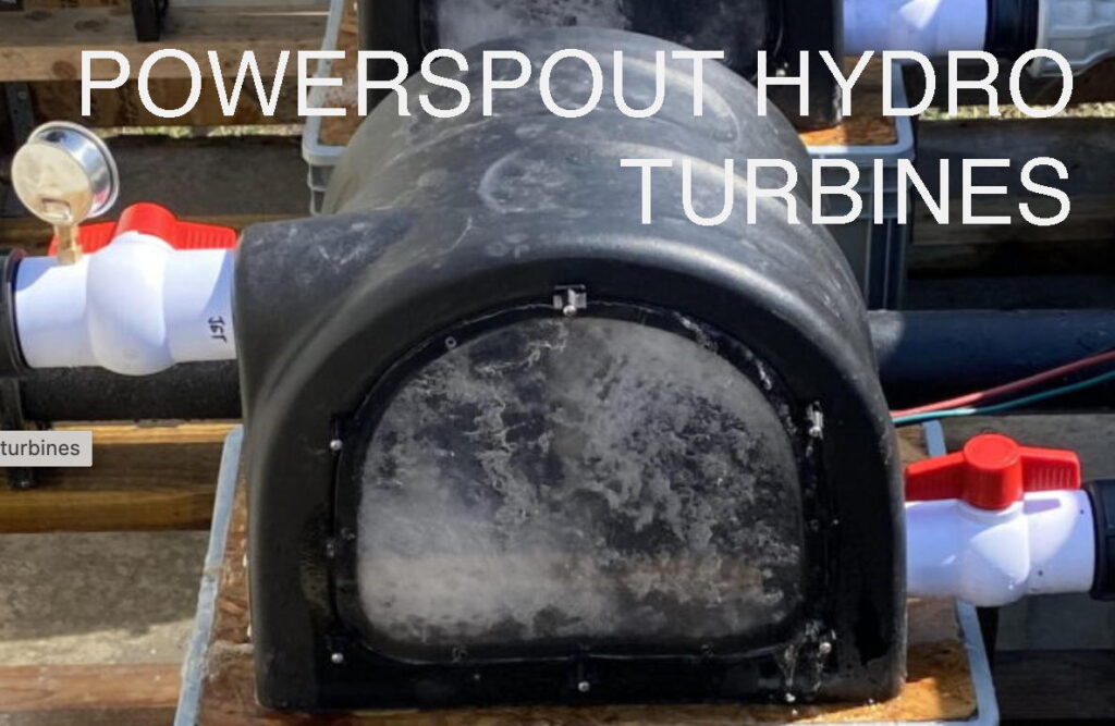
Could you confirm whether the low head pressure/vacuum powerspout is available on the UK market yet and if so what would be the UK price. Looking at 2mtr pressure 4mtr vacuum but flexible with these figures.
hi John,
The PowerSpout products are available globally. They are built to suit the needs of individual sites and then drop shipped directly to site by DHL. Yes I can sell you a PowerSpout LH turbine tailored to your needs for site head, voltage etc. Powerspout rely on local dealers to manage sales and support of local customers.
A good place to start would be to visit the advanced calculator and to read the manuals available as online pdfs. However if you have any questions or want to discuss your specific site with me you can call me or email me for help.
Price for the turbine alone would be £1,170 plus VAT. The Price list and shipping surcharges are in dollars so this changes gradually, but not much.
Cheers
Hugh
Salve Hugh,
Ti scrivo dalla Sardegna Italia
Innanzitutto Complimenti per l’opera di del manuale : Soluzioni per turbine eoliche,
che ho acquistato in italiano ( è favoloso.)
Non so se ho facoltà a chiederti una delucidazione riguardo il TSR.
E’ una conferma che non riesco a trovare in tutto il web , ti spiego :
Non trovo spiegazioni chiare, tra il rapporto TSR di un rotore che gira senza carico e un rotore che gira con un carico ( carica le batterie ).
ESEMPIO : nel manuale , le turbine delle macchine 2400 – 3000 – 3600 e 4200
hanno un TSR pari a 7 (volte la velocità del vento )
DOMANDA : questo TSR 7 è valutato per la turbina pura senza carico ? ho con carico ?
Se il TSR 7 è senza carico , non è che il tsr si dimezza col carico ?
Sto costruendo; seguendo il suo manuale un rotore 32 poli con dischi a 600 mm ( N°64 magneti 50x25x12.7 mm
tempo fa ho costruito una turbina verticale tipo Lenz 2 D.1,80 m – H 2 m, gira vuoto con TSR di 0,8 e dovrei calcolare il generatore . ( ho paura di sbagliare i calcoli)
( secondo la traduzione di google ) la turbina lenz dello stesso tipo con dimensioni : D. 0,90 m e altezza 1,2 m gira caricata con un tsr di 0,8 e scaricata a 1,6 giustamente il doppio della mia. Domanda: essendo la mia turbina di un diametro più ampio e anche più alta come potrei sapere il vero tsr caricato ?
Ti sarei molto gratto se potresti darmi una delucidazione in merito.
In attesa ti ringrazio e porgo distinti Saluti
Google translate says:
I write from Sardinia Italy
First Congratulations on the work of the manual: Solutions for wind turbines,
I purchased in Italian (is fabulous.)
I do not know if I have the faculty to ask an explanation about the TSR.
I ‘a confirmation that I can not find all over the web, I’ll explain:
I do not find clear explanations, including the TSR ratio of a rotor that spins without load and a rotor that rotates with a load (charging batteries).
EXAMPLE: in the manual, the turbines of the machines 2400 – 3000 – 3600 and 4200
have a TSR equal to 7 (times the wind speed)
QUESTION: This TSR 7 is evaluated for pure turbine without load? I load?
If the TSR 7 is unloaded, it is not that the tsr is halved with the load?
I’m building; following his hand a rotor 32 poles with 600 mm discs (# 64 magnets 50x25x12.7 mm
time ago I built a vertical turbine type Lenz D.1,80 m 2 – H 2 m, turn vacuum with TSR of 0.8 and should calculate the generator. (I’m afraid to make mistakes calculations)
(According to the translation by google) the lenz turbine of the same type with dimensions: D. 0.90 m and height 1.2 m turns loaded with a tsr of 0.8 to 1.6 and discharged rightly twice my. Question: being my turbine of a larger diameter and also more high how could I know the real load tsr?
I would be very scratch if you could give me an explanation about.
Pending thank you and I extend my best greetings
hi claudio,
The blades my 2005 book and in the Recipe book are designed to work well at TSR = 7. They actually work Ok at TSR from about 5 through to about 9. If they are unloaded they will run at a higher tip speed ratio around 11 maybe – I don’t really know exactly. But that is not so important. If you read the pages on design in my Recipe Book, P.54 onward, you will see that I need to consider TSR = 8.5 in 3m/s wind speed and then the TSR is OK for winds from 3m/s though to 10m/s.
I hope this helps.
Hugh
Dear Hugh,
I am a brasilian biologist and together with two friends we created an small non-profite non-governmental organization called Florear: sustainable practices. We are contacting you to talk about a project that we want to execute on a low income community in Pernambuco (Brazil). We want to enable the population of the island to construct and maintain their own eolic turbine.
Do you have an email that we could write to?
Thank you for your attention,
Cheers
Dear
I have question please
Is it possible to rotate the wind turbine by pedal.
Best regards
Khaled
try this site http://turbike.org/category/design/
and this one http://www.gulland.ca/homenergy/lindabike.htm
Dear Sir,
I’m building 3kW horizontal axis wind turbine. I want to know more about Axial flux generator design. From your book I got basic formulas and everything. I completed the design of it, want to verify my calculation. I kept it in excel. kindly give your mail id to forward you.
Hello,
I’m charging a 12V battery with my wind turbine. I am using 14AWG wire for my stator, which is reccomended for up to 32 amps. I think it’s safe to assume I should not allow beyond 32 amps. At 7mph and approximately 135RPM I should reach 14.4 volts. At my 14.4 volt cut in, how much of a current should I be aiming for? I understand current depends on voltage and resistance, I just don’t know if it would be a good or a bad thing to somehow reach 32A at cut in speed.
Also, side question: by faradays law, the greater the wind speed, the greater the induced EMF voltage. Is it okay if voltage increased far beyond 14.4V or would that ruin the battery?
Thanks,
Mike
hi
If your stator is wound in series/star 3-phase and you have one 14 ga wire in hand then I would not exceed 25 amps continuous. Wire size ampacity inside a stator is different from wiring in other situations. It has less surface area. But we do rely on some good cooling from the wind.
When you reach cut-in, you are just producing enough voltage to start to charge the battery so technically the current is zero at that point. you need more wind and more rpm and more open circuit voltage to be able to overcome the losses and actually charge the battery.
The battery will control the voltage of the turbine and not the other way around. If the turbine voltage is 16 volts for example (open circuit) and you connect to the battery then you have 1.6 volts to push current into that battery. If you know the impedance of the circuit you know the amps. But it all depends on being able to sustain that rpm with the load on it. Current equates to torque on the blades too.
The battery voltage will more likely be about 12.5 at rest and then it will rise gradually (or rapidly) on charge until your controller limits it to 14.4 V by diverting current to a dump load. It rises as it charges up, depending on the state of charge and the charging current, but the battery voltage basically determines the voltage of the wind turbine to which it is connected.
I hope this helps.
Hugh
Thanks Hugh. Using the basic equation for current of I=V/R, if turbine voltage is 16V do I use 1.6V (16V-14.4V) as my V in the equation instead of 16?
This means that at 14.4V my current is I=0/R=0. Then it increases from there, and I should design my furl so that current does not continuously exceed approximately 25A.
The voltage that drives current in a battery charging circuit is the open circuit voltage of the source, less the battery voltage. The current is found by dividing this by the impedance which is mostly resistance but there will be a slight reactive component if you want to get fussy. Crudely speaking if your cable and stator combined resistance is 0.2 ohms and your open circuit voltage is 16 and your battery is 14 then the voltage driving the current is 2 volts and the current would be 10 amps (2/.2=10) But this depends on your being able to deliver that much poiwer otherwise it will slow down and find an equilibrium.
Yes try to furl at 25 amps. It’s always a bit random and may well need some fiddling with. surges up to 40 or more are fine but try not to sit at a level above 25 for too long.
Ii hope this helps.
You’ve been much help. I’ve just got one last technical question.
My cut in speed is 135RPM. Calculations show that at 245RPM open circuit voltage of the source is 26.5V, making my driving voltage 12.1V. I currently have a resistance of .484 Ohms. This means that my current = 12.1V / .484 Ohms = 25A.
Power = V*A = 12.1V * 25A = 302.5W.
The power is clearly very low, but my maximum amperage is reached at only 245RPM. Would it be a good idea to increase resistance so that my current reaches 25A at a higher voltage?
For instance,
At 480RPM, driving voltage is 37.5V. If I have a resistance of 1.5 Ohms, then current = 37.5/1.5 = 25A.
Power = V*A = 37.5V*25A = 937.5W.
Increasing the resistance allows me to reach max current at a higher RPM (higher voltage), resulting in more power.
This is my logic. Can you please tell me if it is flawed?
Thank you
hi Mike,
YOu want to have open circuit voltage equal to battery voltage at cut in. That’s what cut in means. Its the voltage where the machine cuts in to charge the battery so it’s the zero current point on the curve. Below that speed, no current. Above it you get current that depends on the “driving voltage” divided by impedance.
Impedance will be partly resistance but also the reactive impedance of the stator since it is made of coils. They have some self inductance. The effect is very hard to quantify with a rectified waveform but you need to add a bit to allow for that.
Power that the blades need to produce is found by multiplying open circuit voltage by current. But bear in mind that the output power is battery voltage times current and the rest is wasted heating up the stator and the wires. So yes more resistance means more power… wasted.
I hope this helps.
Hugh
Hugh,
I’m building a 3m diameter turbine with 12 50x25x10mm N52 magnets, 14AWG copper wire. My magnets are positioned with a 1mm air gap between stators on each side. 9 coils per stator. Then there is a steel plate outside of each stator.
I’m trying to get a good idea of what a good cut in RPM would be, and why. First thought is to wind my coils such that cut in speed would be really low, like 25 RPM, but I know it needs to be much higher. However, I don’t fully understand the concept of stalling due to the load.
My next decision is whether to have each stator produce 14V separately and then combine them, or to use both stators to produce a single 14V charge. I believe both options are feasible based on early calculations.
I’m leaning towards combining 2 separate 14V charges. My thoughts are that although my efficiency will suffer due to added resistance, the two separate voltages will be able to produce more power. Also, with the added benefit of a 24V system’s lower power transmission resistance. Thoughts?
I know this is a lot to ask. I thank you very much for your time and assistance.
Thank you,
Adam
Hi
Nobody seems to want to build a bicycle with 20:1 gearing and be able to go at 100 mph whilst pedalling slowly. I wonder why? If they did they would find that they cannot provide enough torque.
Using a higher voltage output at lower speed is similar. Actually mechanical power is made of speed and torque combined whereas electrical is made of voltage and current. Similar relationship. current produces torque and speed produces voltage.
If the speed is too low and torque too high then yes the blades will stall just like when you try to pedal slowly and go at 100 mph. By multiplying the speed upward you multiply the torque downward by the same amount. Your input speed is very low and torque is very high. You can’t pedal that hard. Same with the wind. In low winds it has very little torque and very little power and gearing it up or stepping up the voltage will not change that.
What you have to do is match the ideal speed for the blades to run with the torque they can produce at that windspeed and you will get the most output that way. Actually the power in the wind increases with the cube of the rpm which is hard to match up neatly, but there are some tricks to help, and it does not have to match exactly.
I hope this helps.
Hugh
Let me see if I understand.. A lower cut in speed (25RPM) will make it more difficult for the wind to turn the blades. This is due to electrical forces rather than mechanical forces that I am used to. A higher cut in speed (400RPM) will make it easy for the wind to turn the blades, but little work would be accomplished.
So I need to find a proper balance between the two. However, I am unsure how to find the ideal speed short of having a speed-torque graph being placed in front of me. If I cannot come up with a solution, would it be a bad idea to just go with a seemingly “safe” number such as 170RPM?
Also, could you let me know your thoughts on having each stator produce 14V separately and then combining them into 28V? (From the last 2 paragraphs from my post)
Thank you!
hi
Maybe the best way to approach it is tip speed ratio. The blades work best when their tips run at (say) 7 times the windspeed. Depending on the blade design. I have no idea what blades you are planning to use, and some are slower. So then you can figure out your best rpm in any given windspeed. RPM is proportional to windspeed. In an ideal world that is.
This is the obvious way to find the optimum cut-in rpm. But bear in mind that as the windspeed increases from 3 to 5 metres per second (7-11 mph) you will ideally want to increase rpm by 67% but this is unlikely to happen if you are using a battery-charging alternator. More likely the rpm change for this sort of power change will be minor – around 20%. Again this depends on the alternator and mostly on its internal impedance and so forth. So it is necessary to compromise and have a high tip speed ratio at cut-in and then run a bit low on tsr as the wind goes through 5 m/s.
This is all explained in my books by the way.
cheers
Hugh
Thanks Hugh,
I’ve established a cut in speed but currently my EMF voltage at that RPM is around 10V instead of 14.4V. I need to increase this, but I would like to do this without adding a lot of wire resistance. So instead of increasing the number of turns I am considering increasing dA/dt. By increasing the radius of my rotor, I can increase the angular velocity of the magnets passing the coils — resulting in a higher induced EMF voltage. Is it as simple as this, or are there trade-offs that I am not considering?
I have 9 coils per stator, 3-phase. By increasing the radius of the rotor (and thus the stator as well), there will be greater spacing between the coils. Is this a problem, or is it necessary that the coils be placed very closely to each other?
Thanks,
Adam
hi Adam,
Increasing the velocity of the magnets without increasing their size or number will not increase the amount of flux change per revolution. so no this will not directly increase your voltage output. It will make the machine bigger which will allow for more turns of thicker wire in the coils which will have the desired effect. But the coils do get large and there are diminishing returns as the wiring for each turn gets longer and longer. So increasing the number of magnets is a better option. Or using larger magnet area.
Going to 16 magnets and 12 coils will dramatically increase the potential of your alternator. whether this is necessary depends on what size machine you are building and whether you get enough wind to justify it. Also bear in mind that a very efficient alternator connected to small blades will likely stall them out rather than being able to harvest the power in stronger winds. If you are trying to work over a wide range of windspeeds then it is a challenge to maintain optimum blade speed with an efficient alternator directly connected to the battery.
cheers
Hugh
Hi! I am an amateur who wants to design my own vawt. My idea was to use a 1.5meter diameter rotor that is 1.5m high, using the Darius helix shape. I want the generator to be 24v at 1 kW, so how many coils, and how many turns in the stator. I also had the idea of hocking up a magnetic gearbox to the unit which would turn the generator at three times the speed of the rotor. would this gearbox affect the coils and turns required. I am a high school graduate so have no knowledge at all about the magnets used in the generator. I am looking for a nice easy template that anyone can build.
Dear Hugh,
just a short note to inform that I have now finished the 2.4 mtr turbine. Thanks for your input via the Navitron pages. The turbine is now up and running and steadily producing amps for me. I have 2 car alternator type turbines I bought mistakenly some years ago that have neo type magnets in. I’m now considering dismantling them for the magnets and reusing them to build a larger (4 mtr ) turbine to your design.
Thank you again.
http://postimg.org/image/4ex05go2d/
here’s a piccy of finished unit and here’s the Navitron thread.
http://www.navitron.org.uk/forum/index.php/topic,24270.105.html.
Thank you again.
Andy Finch
Hello,
I love this writ http://scoraigwind.co.uk/installing-and-configuring-a-tristar-controller-for-a-wind-system/
I would like to do this soon as I have an un-used 48v wind generator that is waiting for a new set of batteries.
But the aforementioned is not my intent for writing, would you mind if I copy the information you have on tristar setup pages? It would be helpful to have it in a format accessible when without internet access. Of course, all the credits would remain intact and links (of those that interest me) will still lead back to your site regardless (in other words, I’m not trying to plagiarize….I would just like to host the information should you fall of the planet earth and cease to exist “;-).
Amen.
Simply put, I’m wondering if you would allow me to copy the text/pictures in your information of the setup of the tristar?
Sorry for the former geriatric verbose moment.
oh sorry for the delay replying to this. Yes you can copy my stuff for sure. I would hope that you will attribute it to me and link to my site. cheers, Hugh
Boy….talk about losing touch! I guess there wasn’t an email confirmation that you had even replied to my message on here….
Hey Hugh, I have a 48v wind generator (dc alternator type) that hasn’t a diversion load (mostly because I’m clueless about diversions). It does have a hefty blocking diode in the path but everything I try doesn’t seem to be very assuring with that unpredictable form of electricity.
So far I’ve bothered to fiddle with it three times. At first, I had it go directly to a 48v battery bank and kept two grid-tie inverters at the 24v point on the bank (each inverter has a variance of about 26v-55v). It failed when something melted the battery terminal and actually made a hole into the battery itself! (luckily no bomb)
The second time I decided to connect the dc 48v wind generator up to my mppt 60a 150v tristar. It only took one scare to find that wasn’t the way I wanted to go either (came out to find nothing working, not even voltmeters!)…luckily the tristar must have an automated shutoff or something…after a reset to the battery it was still alive.
Suffice to say, I’m not an expert at wind by any means and find it so far to be too variable/not dependable.
Is there something you can suggest where I can put this 48v generator to anything (except my battery bank an controllers)? What I mean is, do you know of anything I can just connect to this generator and leave alone (like an appliance with a 0-to-70v tolerance)?
It really is a great quiet spinner (when it’s not tied down like it is now) and it’s 10 clear blades are not an eyesore so if you can’t think of anything I can use this for, maybe it’s time for you to invest in me to send this to your house?
Signed,
frustrated
hi Kenny,
Sorry I did think you would get a notification for my last reply. not sure why not.
Anyway you do need to get a diversion load controller organised is all I can say. That’s the right way to do it and doing it the worng way is expensive and dangerous. I have described how to do it. Read that and if it makes no sense then start asking me questions.
Do not run inverters off half the battery. Get a 48 volt inverter or a 24 volt wind turbine. YOu are just going to get even more frustrated if you don’t.
Have fun!
Hugh
Hello I have built a timberframed work living space within a large garden which I want to set up off grid power in. The roof is not ideal for panels N/South apex ridge ~30degrees, however there is wind database states 6.5m/s average. Have you got any experience of getting your turbine designs through planning applications we have to do this as the main house has an air source heat pump and your only allowed one or the other inside permitted development not both. I also would have to go through the Micro Generation scheme do you know if this is something I could do myself or would it be necessary to pay an approved installer. Thanks if you can be any help.
hi Merlin,
You will not be able to get MCS blessing on a DIY job since the government made sure that the MCS process will not support DIY but only MCS approved installers. The whole idea of it was to build a professional industry rather than to encourage renewable energy directly. So you do have to pay an approved installer to install an approved product and then you can get feed in tariffs. It’s tricky to get planning permission for a windmill, and even permitted development does require you to jump through some hoops whilst restricting the height to a level where there is no useful wind. to be honest I would not bother unless you live in a place far enough from neighbours that you can just go ahead and put it up without controversy. West facing roofs can give a decent amount of solar energy actually. The % difference is less than you would think relative to south facing.
Have fun
Hugh
Please provide your company’s email address
my email is hugh “at” scoraigwind.co.uk
“Make sure that the Tristar can handle the full current that the loads draw from the battery at the maximum voltage (equalising voltage for example could be over 30 volts on a 24 volt system). If necessary you can use more than one Tristar controller in parallel. Each Tristar will need its own resistive diversion load that is appropriately sized. They can all be wired to the same battery bank.”
In above paragraph from your website you say TriStars in diversion mode can be connected in parallel to deal with higher amps than what they are rated for. our potential max load would be about 95amps so we would need 2 TR60 connected in parallel and each would need a separate dump load. How the parallel connection is done and what rating each dump load would need to have, say, 95/2 amps?
hi
If your maximum input power would be 95 watts then to conform with NEC you would add 50% to that and get 140 amps. But if you keep an eye on it that will not be necessary. You can have one load around 55 amps on a TS60 and one around 40 amp one on a TS45 you’d be OK. Connect both in parallel to the battery but take care not to connect the loads in parallel. they work independently just like two solar panels or solar and a wind turbine would. All batter connections need to have fuses or breakers on them. There is no harm in having too big dump loads for the source but don’t make them too big for the controller.
Hugh
hello iam located in dayton ohio us i was surfing the web a few years back on wind power and found you guys first i would like to thank you for all the info i have gotten it helped me get started i built a 12inch brake rotor head with 6ft blades just on a test pole i acheived between 38 to 40 volts i lossed focus on my project with this rat rod craze but now its back to the worthwhile projects thanks again jim
Hello. I’m a Electrical Engineering MSc. student at University of Rome, Italy. I’m developing my thesis in wind power systems, specially focusing on a small scale wind turbine and alternator made following the indications of your book. I’m trying to implement the Tristar TS 45 solar controller and I’m modelling all my system throught a simulation using the Simulink tool and then I will confront the model with the real system, but in order to do that I need to know how the power electronic of the controller works. So far I haven’t found much information about it. I would like to know if you can help me with any kind of information you may have about this. Thank you very much in advance
hi Sira,
Please could you ask a more specific question? I assume that you understand that the TS acts as a rapidly pulsing switch that pulses current to the load at 300Hz and controls the average current by adjusting the duty cycle of the pulses? Are you asking how the hardware works or about the logic of the voltage regulation? Have you read these documents http://support.morningstarcorp.com/search/?search_product=102 ?
Hugh
Hi Hugh, My name is Mathew Smith from South Australia. I am doing a wind energy project for Bambui (West Africa). I was just curious on how the turbine provides power to the appliance? For example If the turbine produces 400watts does that mean it can run a 400watt appliance? And does it mean 400watt per hour?
Thank you. I find what i have read about what you do very inspirational and noble.
Regal Regards
Mathew
hi Mathew
you need a battery to smooth out supply and demand. The supply has to meet the demand over a longer period (days) but short term the battery takes up the slack.
400 watts per hour is a very ignorant thing to say (sorry!). Watts are already a rate of energy transmission. The rate is power. Energy itself is measured in watt-hours. 400 watts for 5 hour is 2000 watt-hours or 2kWh units of electrical energy.
Hugh