I don’t usually write much at all about the stuff I get up to, but here is a story of my smaller wind turbine having an upgrade last month when I replaced the alternator. I was helped by my friend Jonathan Schrieber.
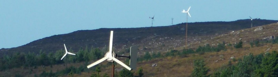
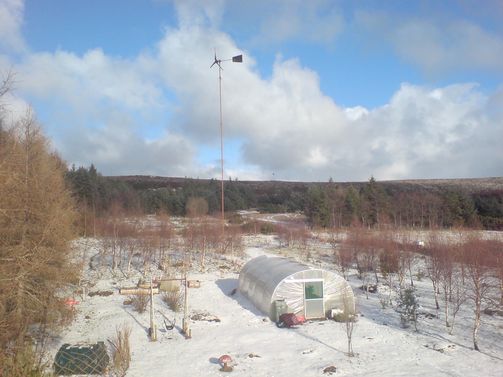
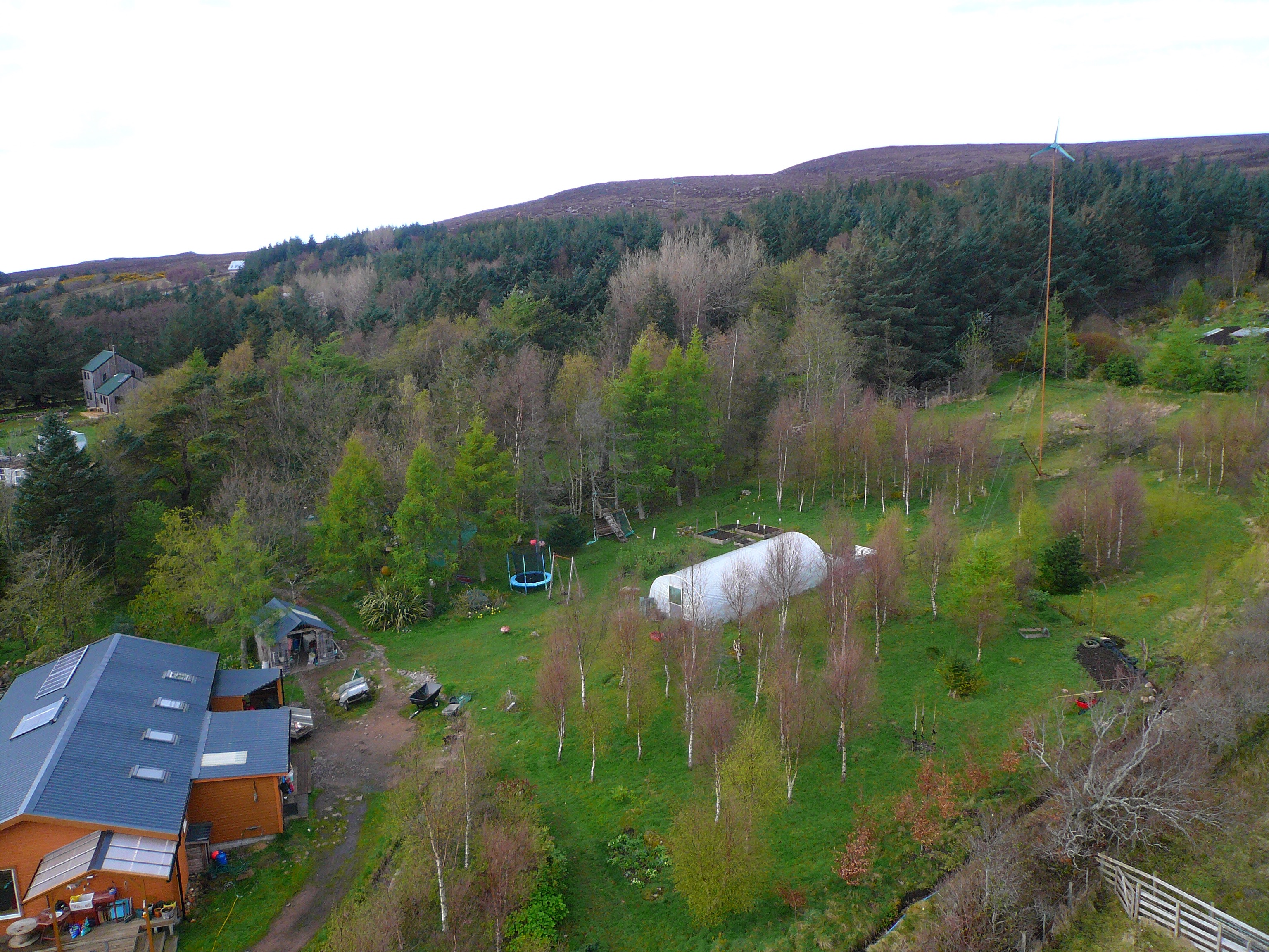
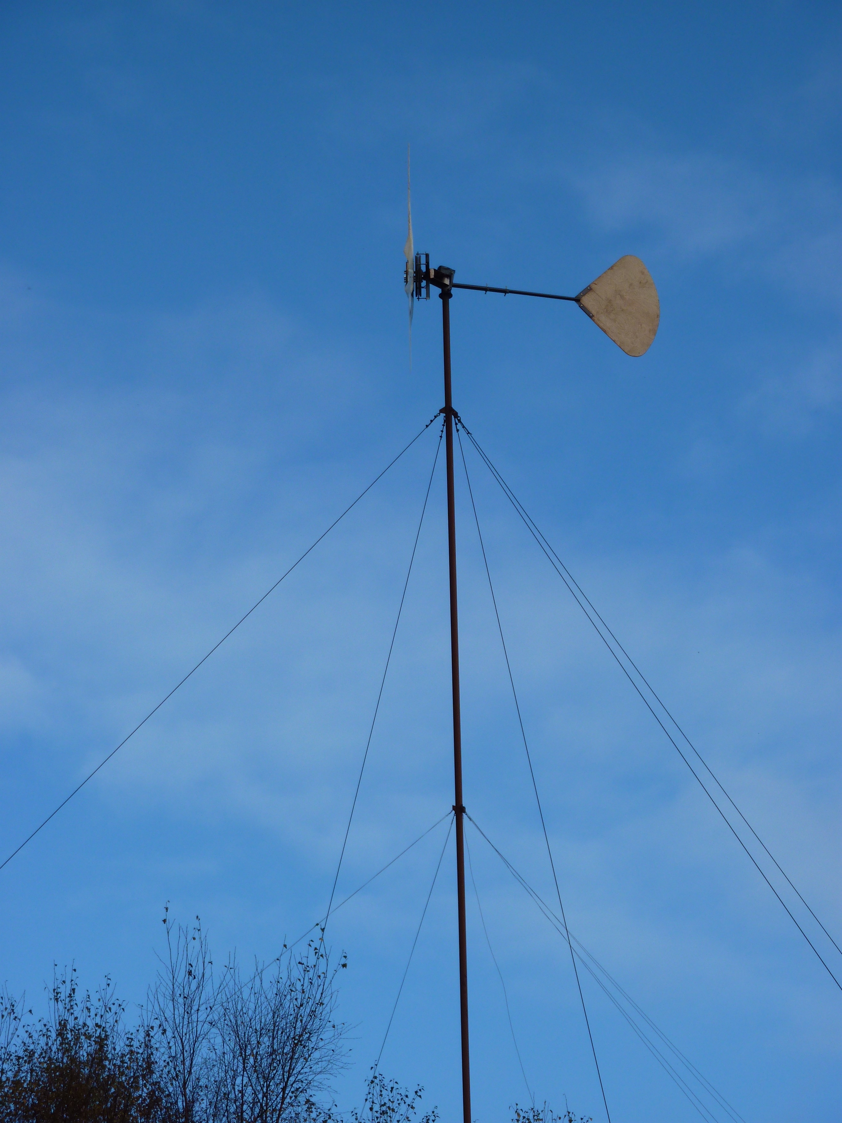
Let’s start with a photo of the African Windpower turbine I erected behind my house in 2007. It’s a design I did for manufacture in Harare in 1996 or so. Already here it has a Scoraig tail and Scoraig wooden blades. It was connected to my 48V batteries. There weren’t so many trees around in 2007 or they were small.
Here’s a picture of the wooden blades carved by my neighbour Michel Grenier. The fibreglass ones from Africa work ok, but they tended to break a lot, which is why we needed to replace them. Wooden ones seem to last longer.
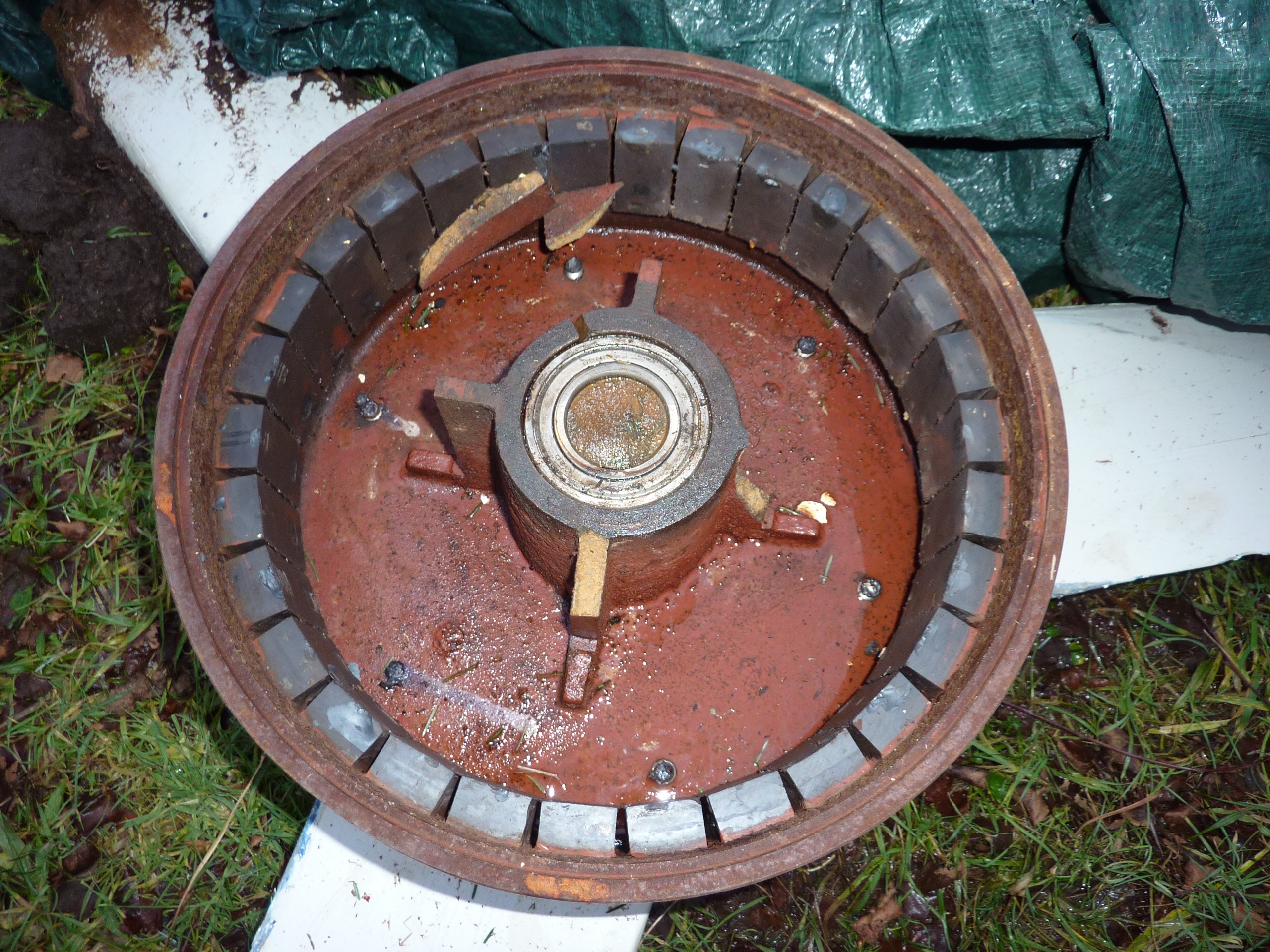
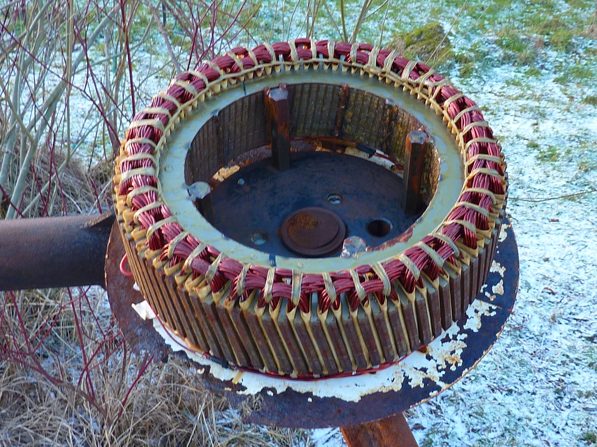
Here’s a shot of the AWP alternator. It’s built with ferrite magnets inside a cast iron “drum” and it has a laminated steel core. It’s really heavy (70kg) and tends to overspeed in high winds due to the fact that the steel core limits its output current. Nowadays I prefer the axial flux design and that’t what we made to replace this one when its stator insulation failed.
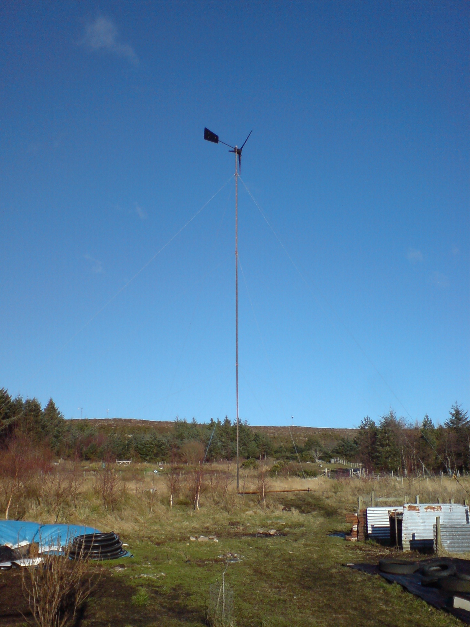
Hoisting it up on a 20 metre tower using a gin pole and Tirfor rope hoist. Tower diameter is 89mm overall (3″ steel pipe) which is a bit slender and snaky.
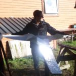
From the rooftop of the house.
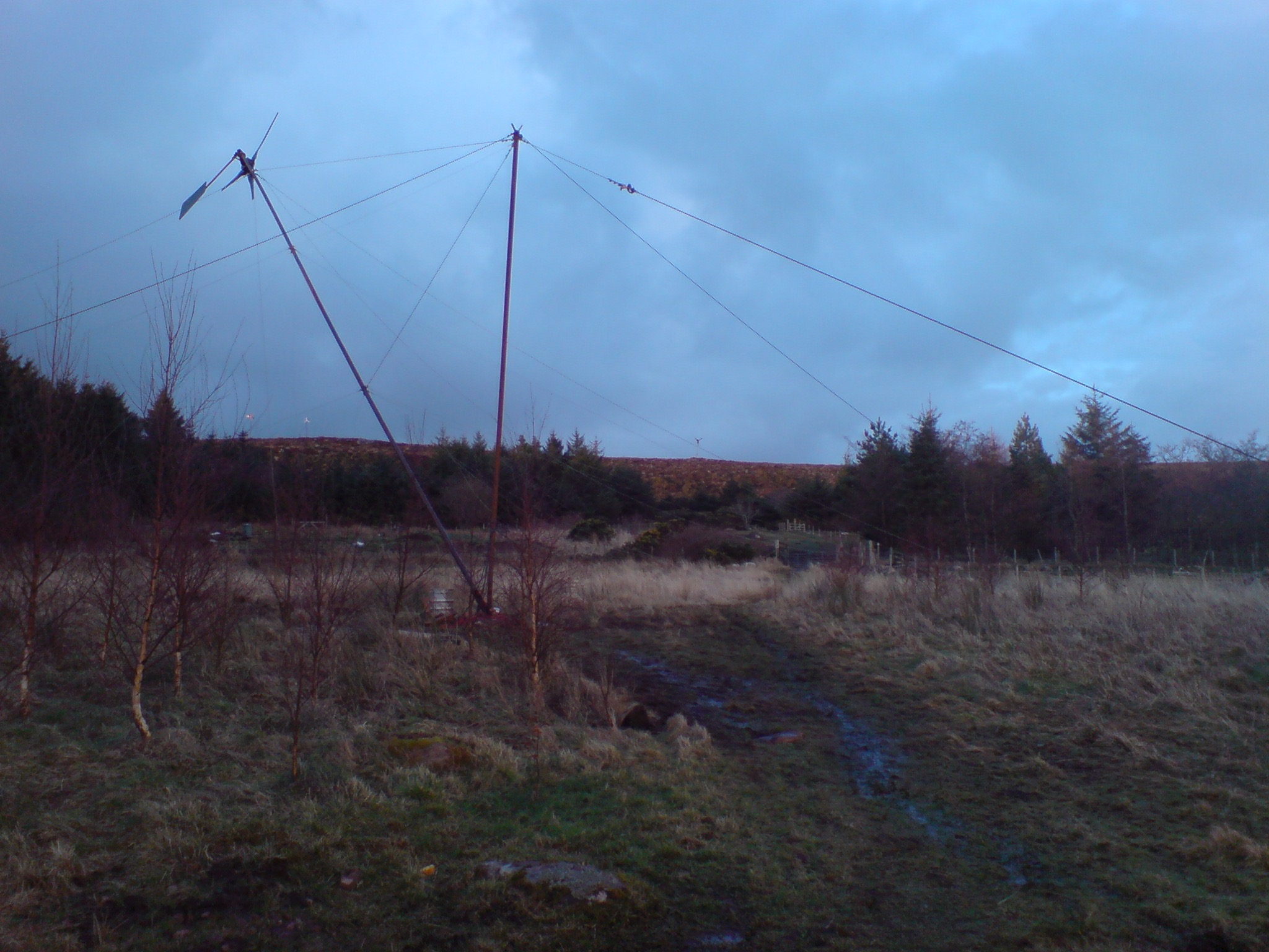
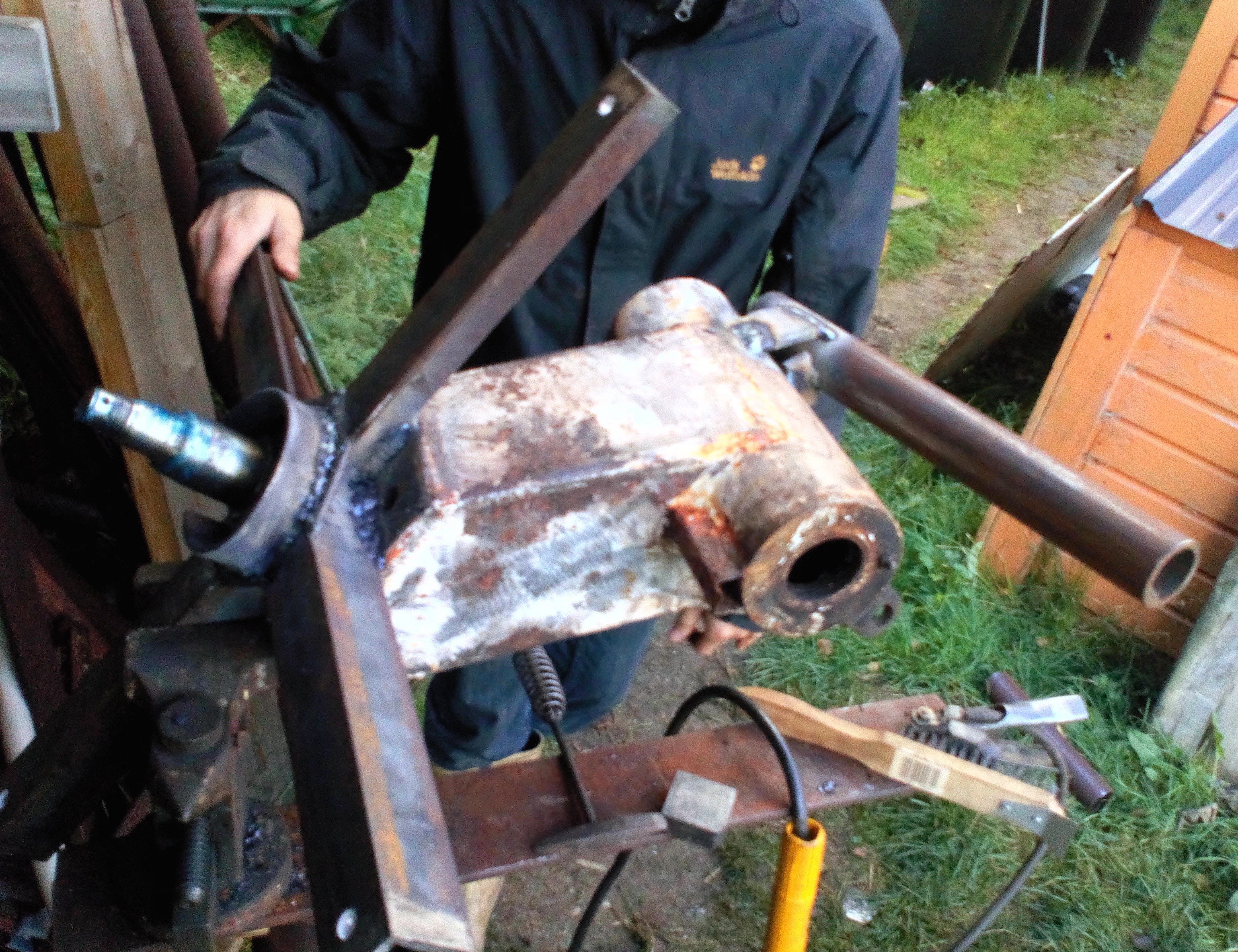
It hasn’t been without it’s dramas over the last ten years. For example here is the result of a severe storm in 2015 when the shaft snapped and the rotating parts fell to the ground. I decided not to run it so hard after that. I’d been using a Midnite Classic to drive it a bit hard and get more power out of it.
By the time I had fixed everyone else’s windmills (quite a bit of damage in that storm, so it took six weeks) and took my one down, the shaft fracture had already rusted a bit. Or maybe it had been cracking for a long time…?
Seen from the big windmill.
The AWP windmill ran nicely for 2 years or more after this fix, but some time in August this year I noticed it was running poorly and producing low power. There is a data logger on it and you can even see what it is producing right now to the right of this column in the little chart. The stator had an internal short that I was unable to remedy without a rewind.
Here is Jonathan winding the first coil for the axial flux replacement alternator following this year’s insulation failure. Rewinding the older stator is extremely laborious and anyway I prefer axial flux nowadays so glad to move on to the newer design shown below.
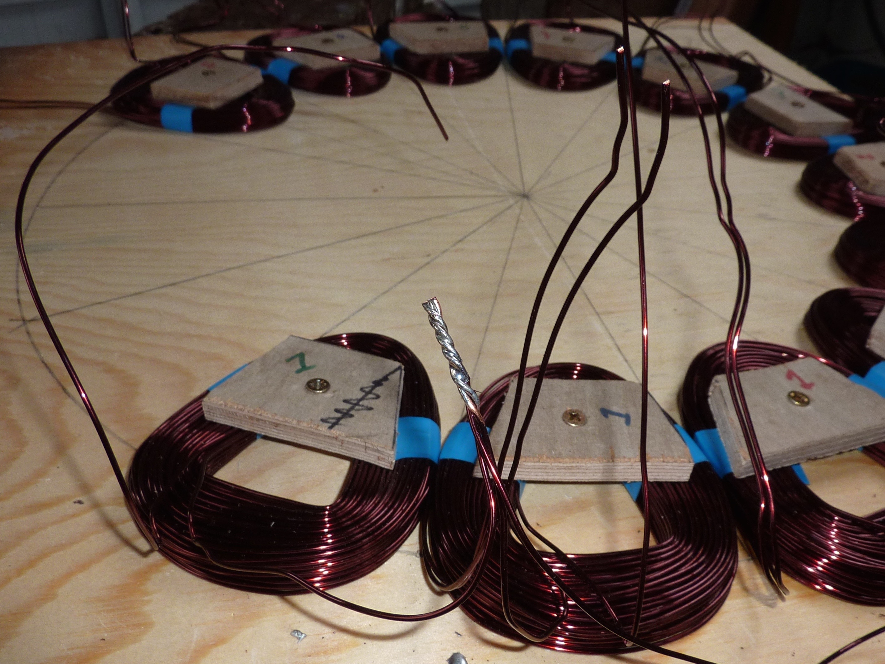
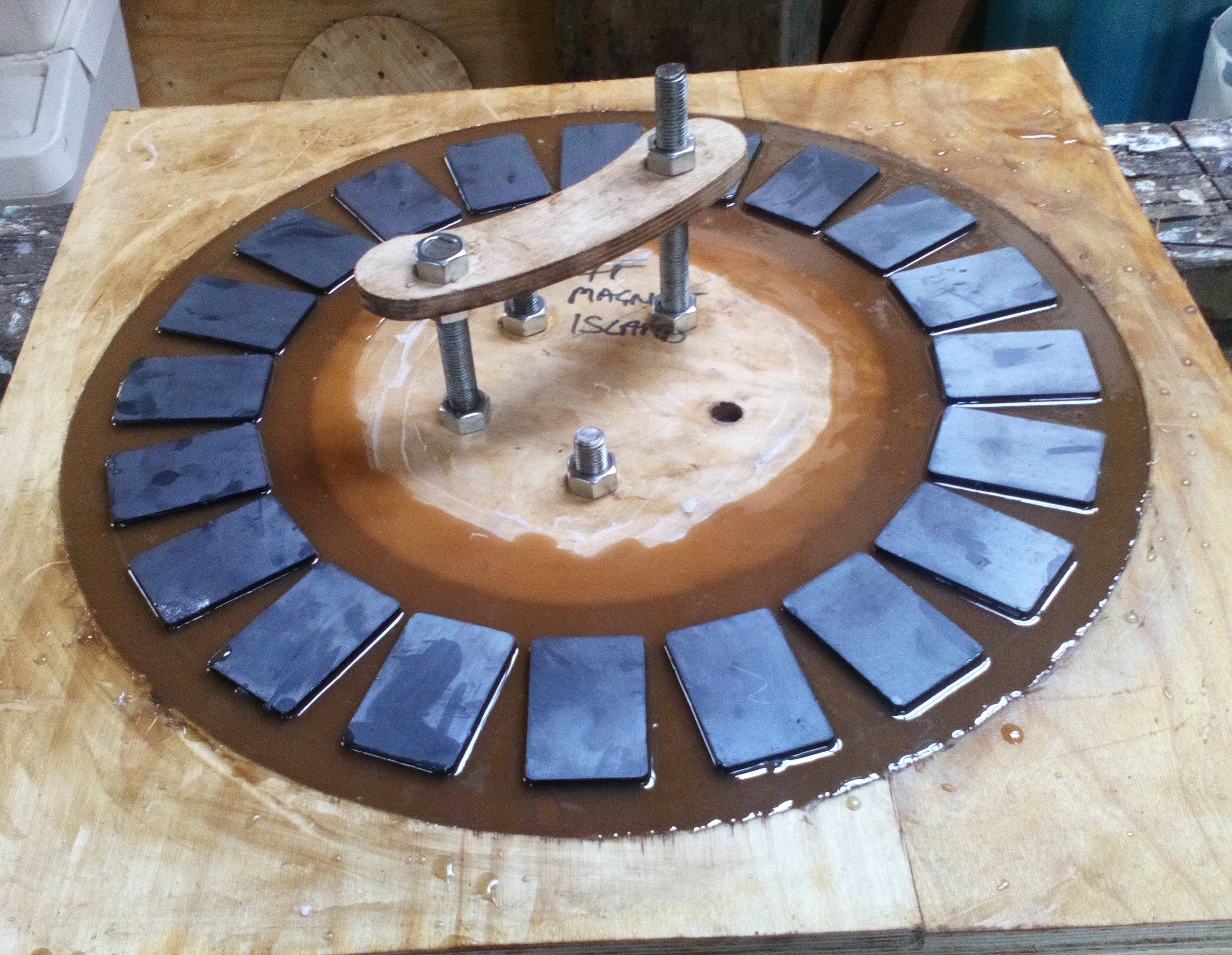
We used 60 turns of 2-in-hand 1.4mm diameter wire. The coils came out just right to fit 15 coils in the stator. We put 20 ferrite magnets on each steel rotor disk.
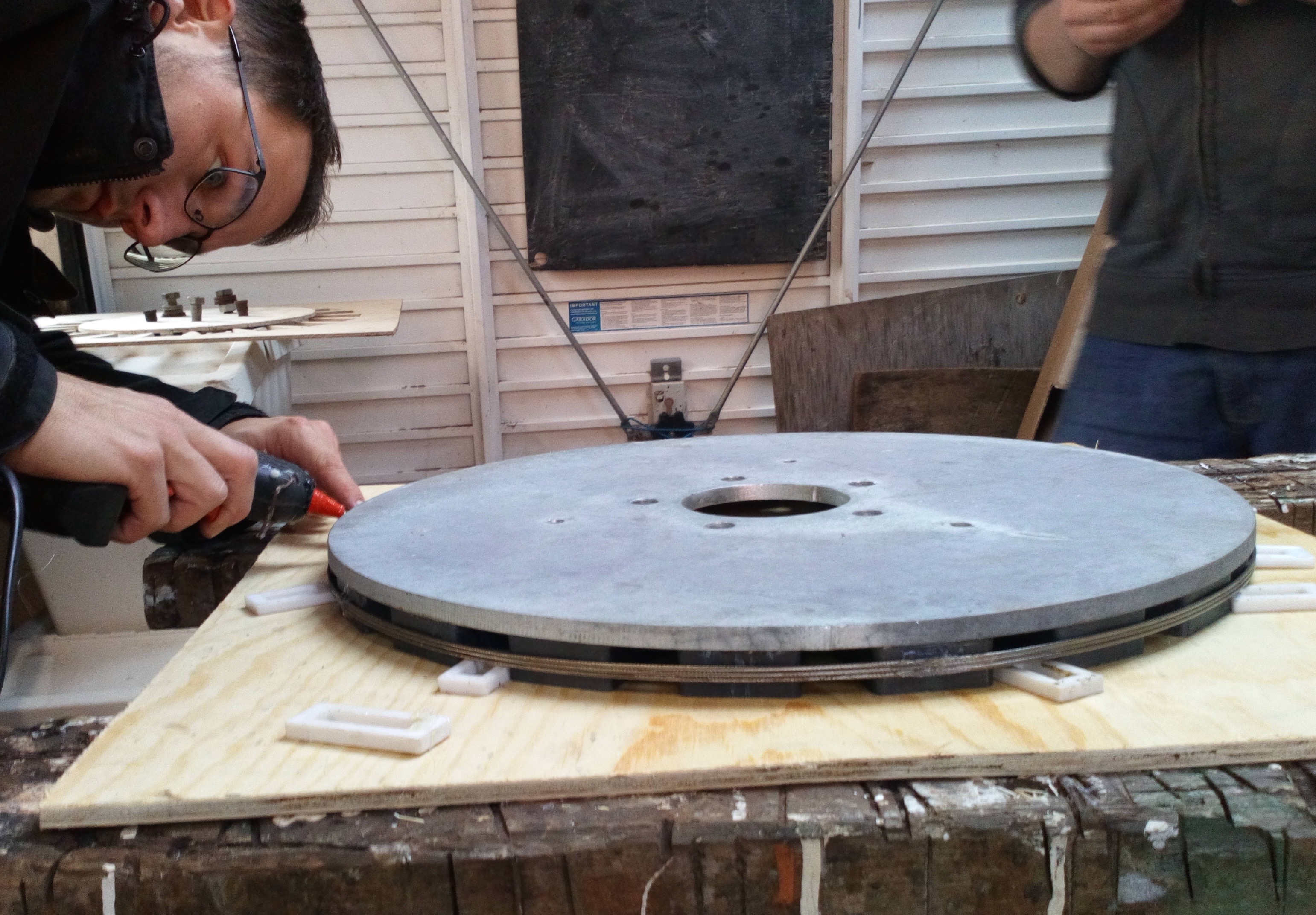
I like to use stainless steel wire reinforcement around the magnets prior to casting them in resin. This has stood the test of time. I don’t use glass cloth with ferrites, because the magnet stand proud in the resin without covering. They don’t need protection from anything, as they are extremely robust. Not a corrosion time-bomb like NdFeB magnets!
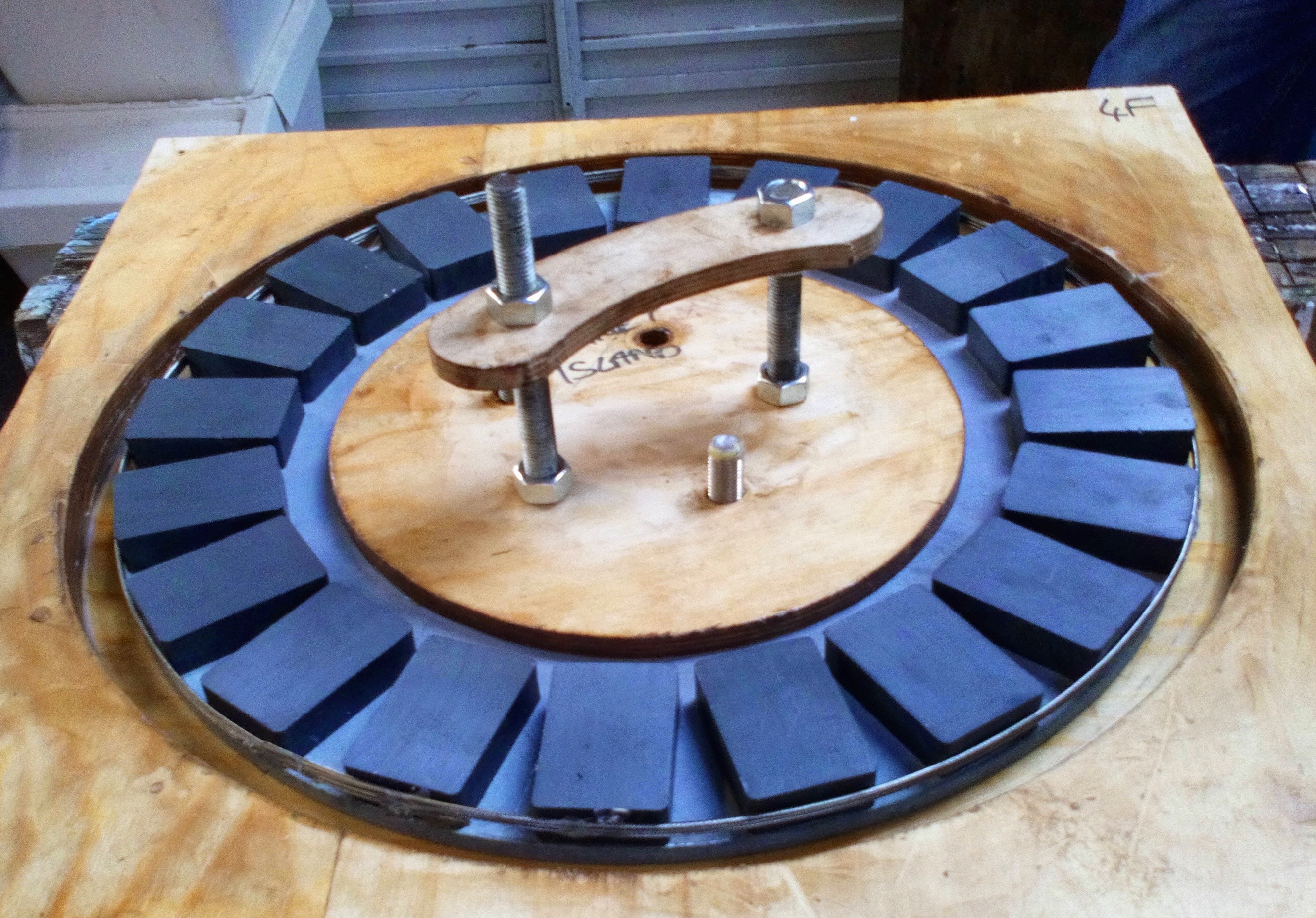
A rotor in the mould ready for resin. The handle makes it easier to lift into place.
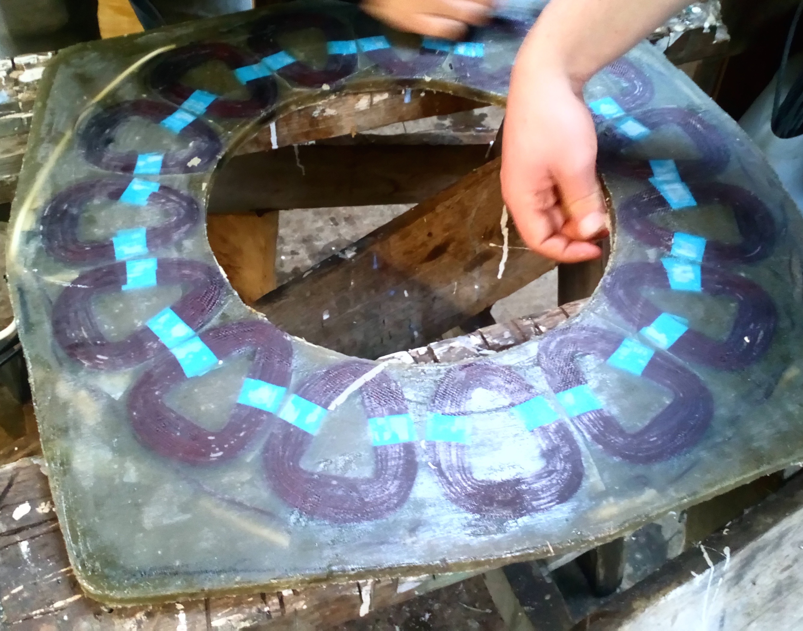
Here’s the stator. 10.2kg weight. Over 7kg of that is copper.
The frame of the machine ready for building the alternator.
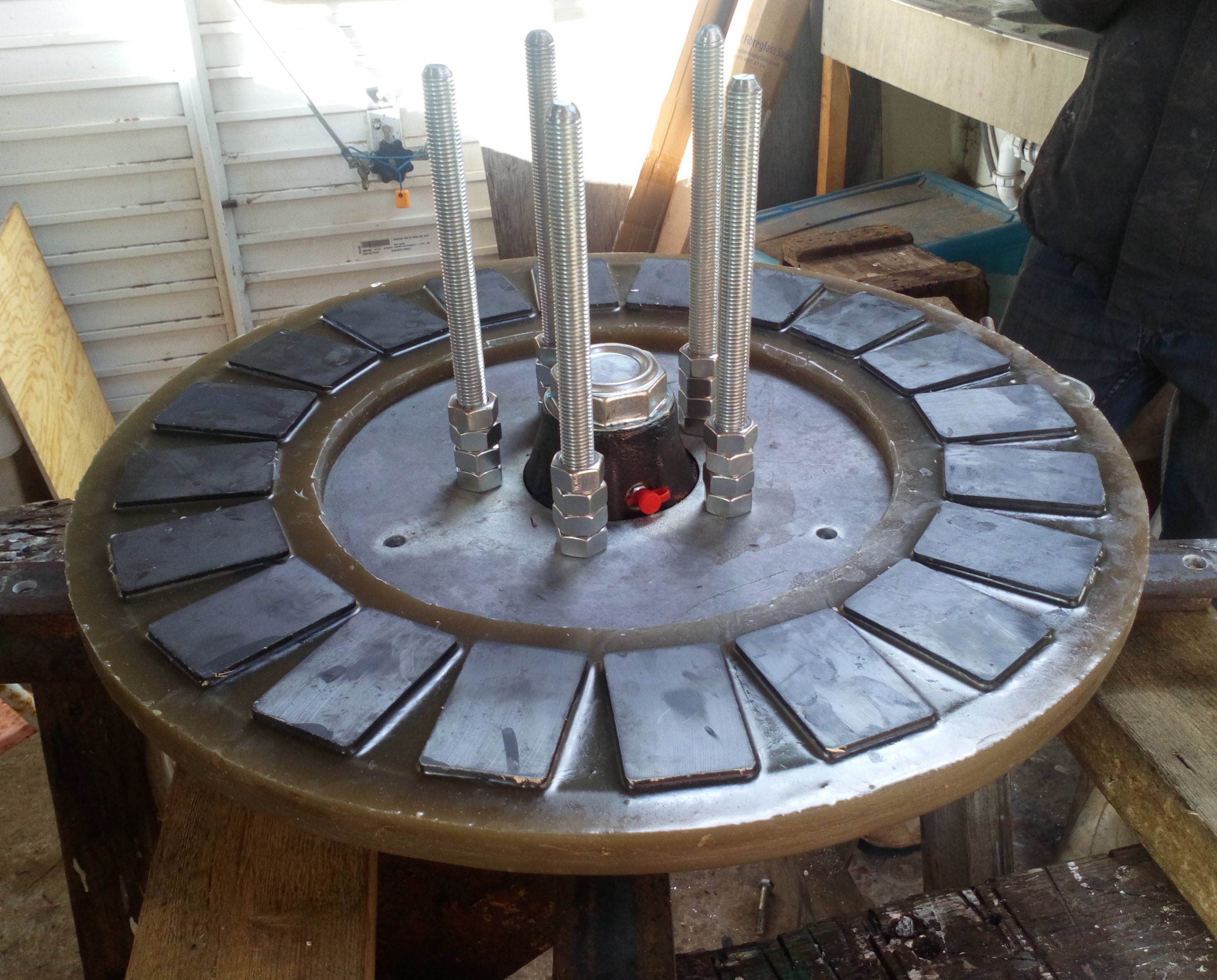
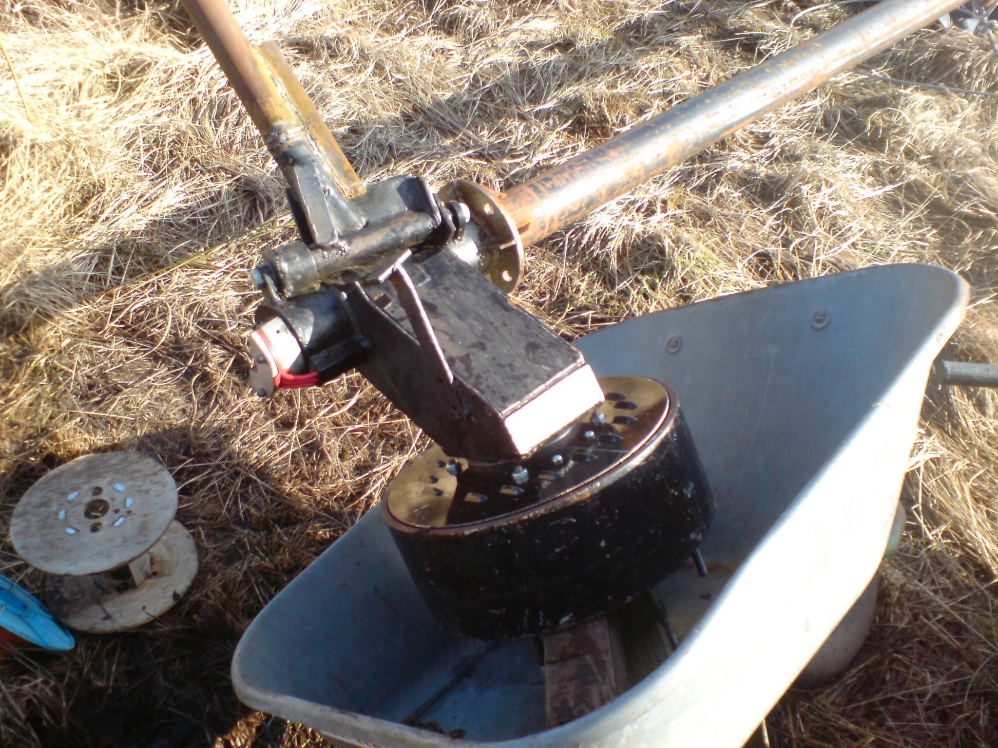
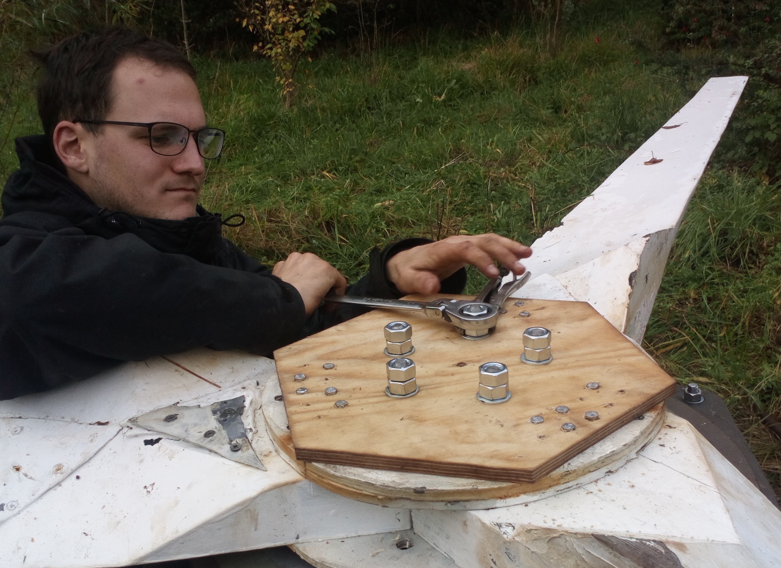
Mounting the back magnet rotor (24.5kg) onto the big trailer hub.
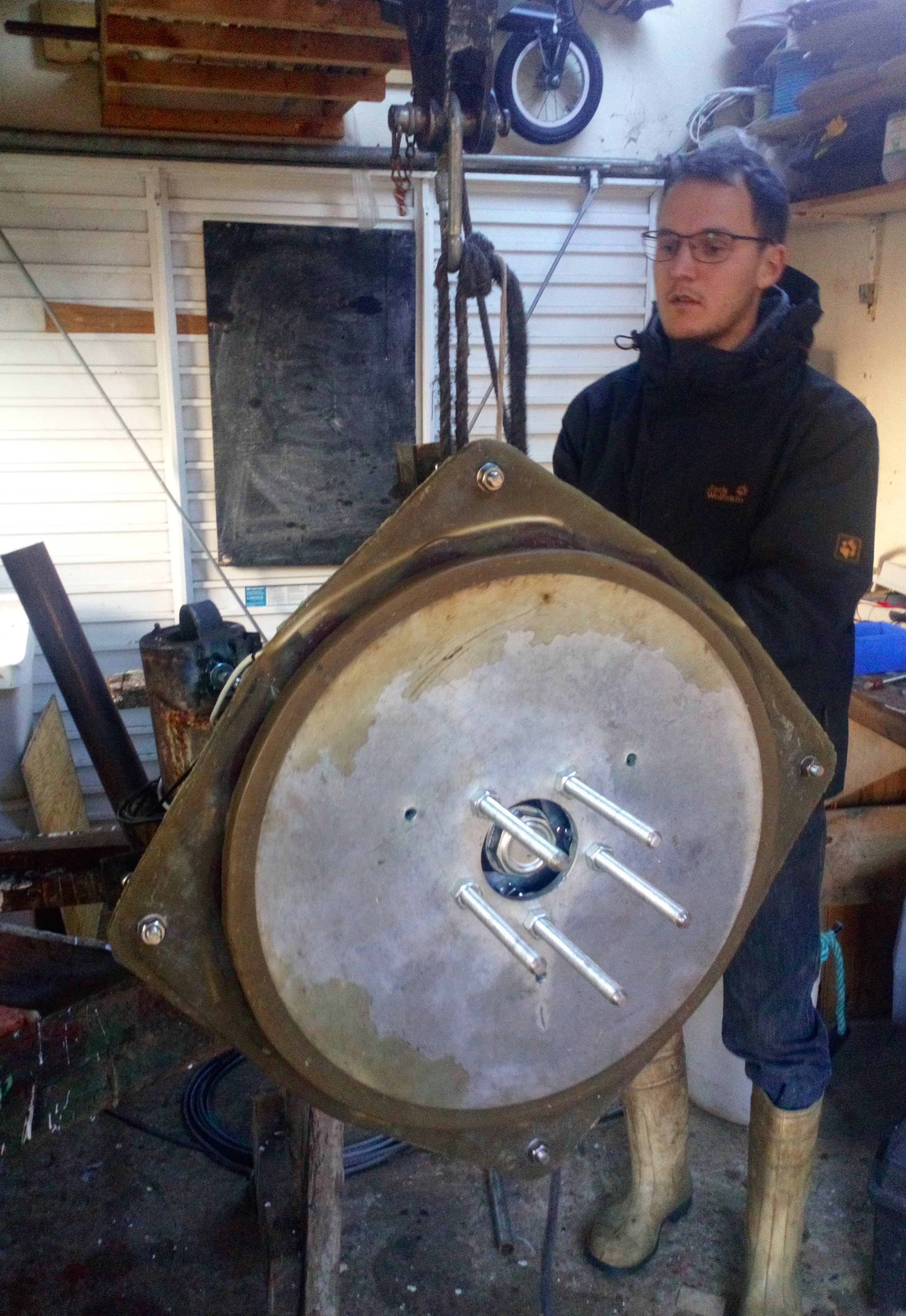
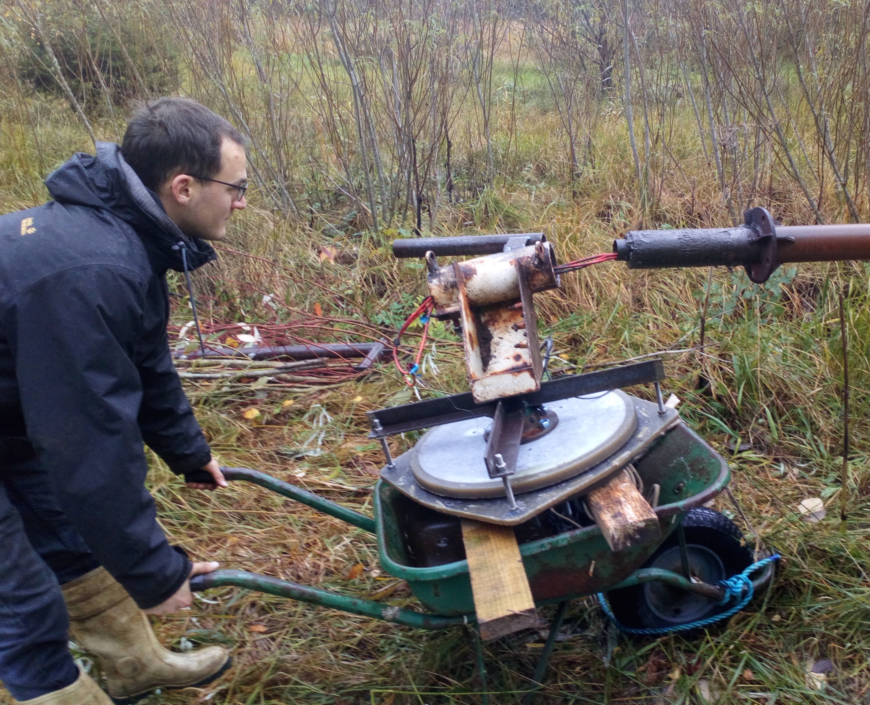
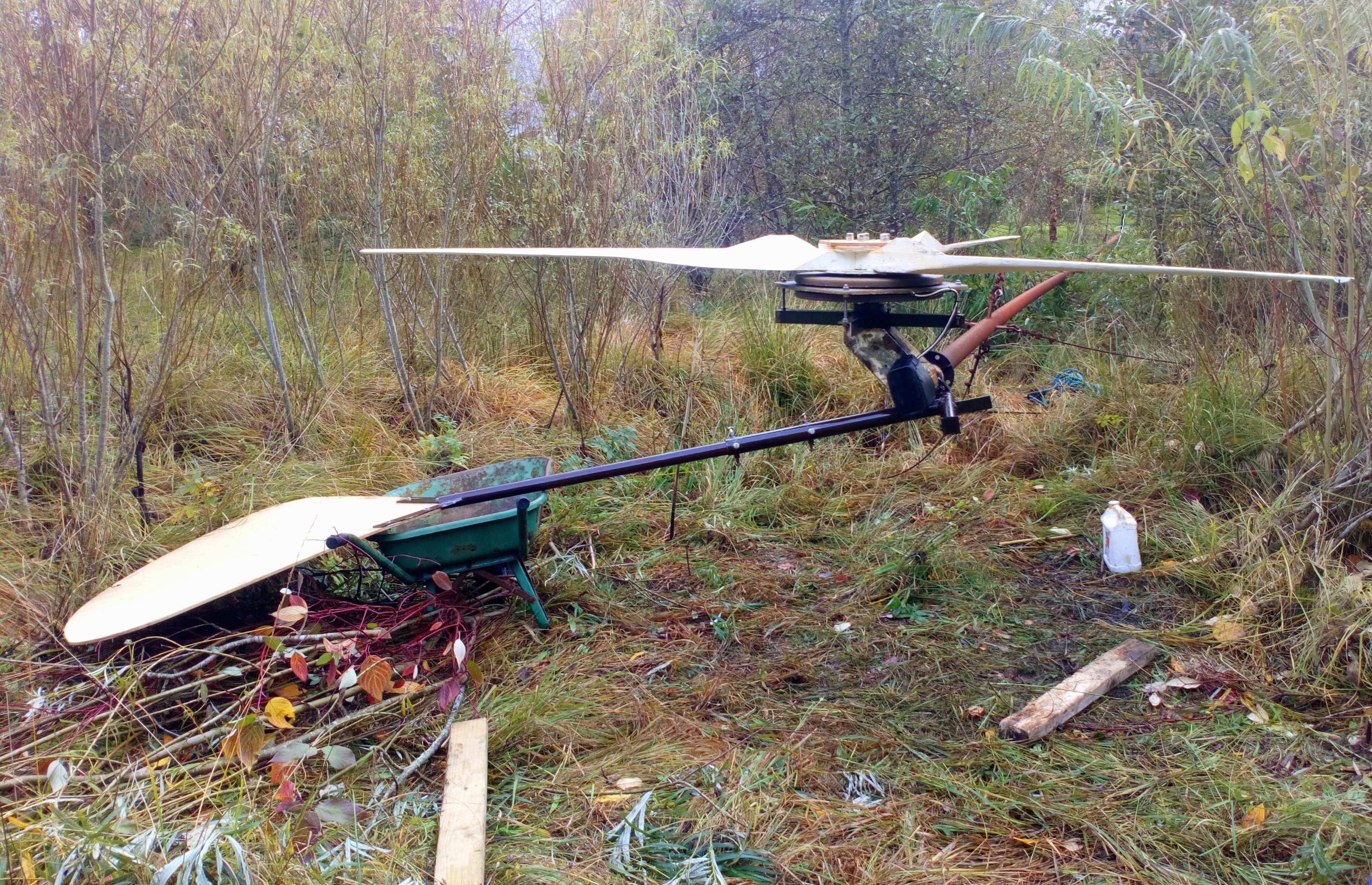
The whole assembled windmill hanging off a hoist, waiting for the wheelbarrow. Over 100kg.
-

- circular level on top of hub.
-
- balancing the blades on a spike.
We didn’t have time to do much to the old blades. They were still in perfect balance when checked sitting on a spike at the exact centre. Leading edges were in good shape so I guess I must have done them within the last five years.
Easing the machine onto the tower top.
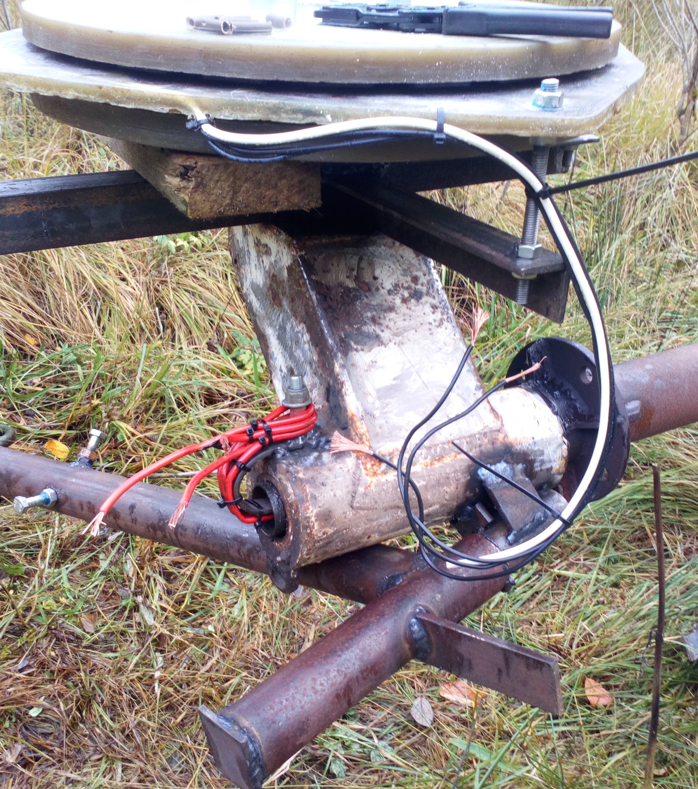
The down-tower wiring strapped onto its supports ready for crimp connections to the stator tails. I use small bore copper pipe to crimp the wires after they are tightly twisted together within the pipe.
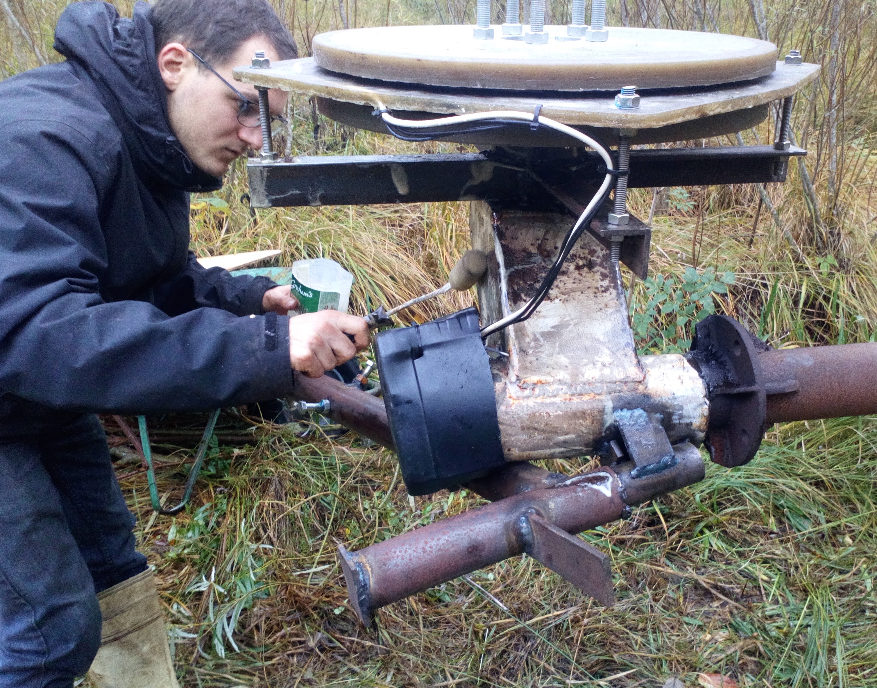
A quick coat of linseed oil on the rusty metalwork.
Fitting the blades. We added an extra piece of birch plywood for luck.
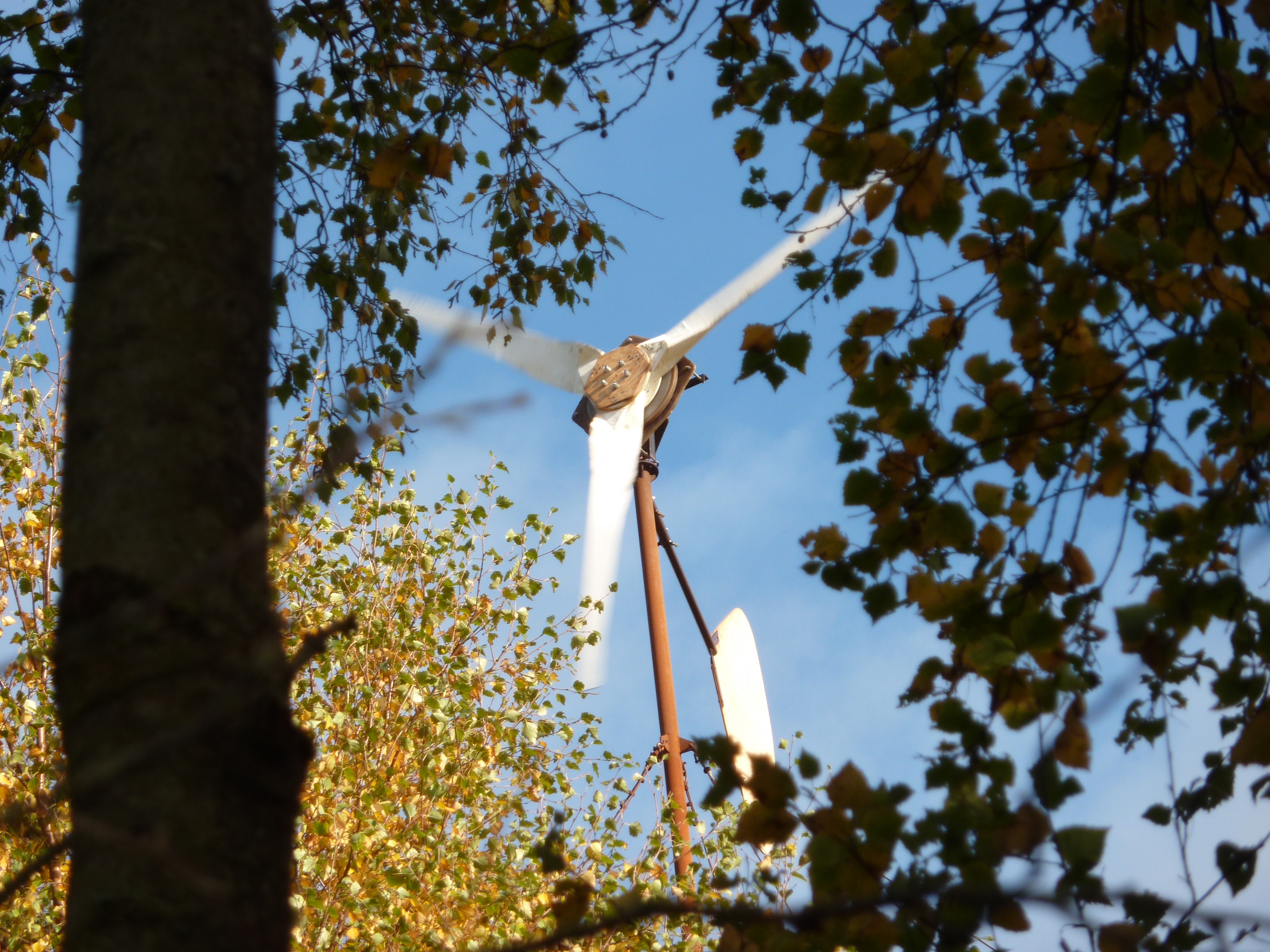
Ready for lift-off. The trees have grown a bit since 2017.
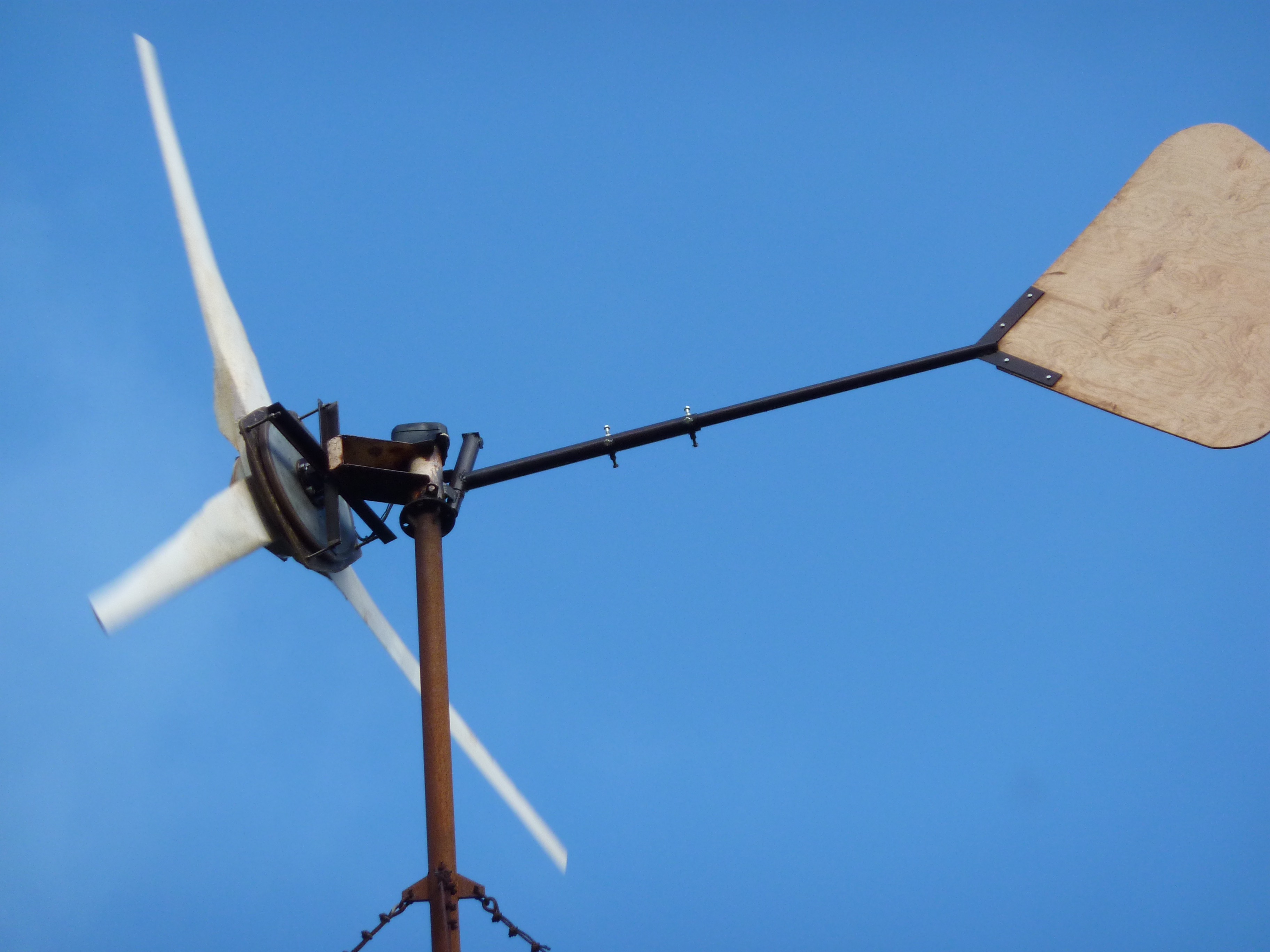
Up and running sweet and smooth. I made the tail telescopic but I don’t think I will need to adjust it. Governs out at about 1200W average power.
 Magnets – 20 per rotor – 75x50x20 ferrite Y30BH C8
Coils 15 of them 60 turns of 2×1.4mm dia. wire 460g each.
Nominal cut-in for 48V DC is 134 rpm. 1200W rated output at 260 rpm
Blade diameter 3.6 metres
Rotor lateral offset for furling 200mm.
Tail hinge angle 15 degrees. Tail moment of weight 29 kg-metres.
Vane area around one square metre of 9mm birch plywood.
I take this is the 4f machine made to suit the 3.6m rotor with two 20inch magnet rotors. nice to see one built.
hi Arthur,
Yes it’s a modification of the 4F. Slightly higher rpm and higher power given enough wind. (Less power in lower winds due to smaller blade diameter though.)
I have only built one other 4F, but several have been built in Estonia, where there is a company that are considering doing them as a commercial product for grid connect.
cheers
Hugh
Evolution in action! Could you please confirm current preferred 2017 magnet material spec/sources. I have a copy of the recipe book from a few years back. Also I see some are more resilient to corrosion.
Also that link to the forum is giving me a 404 eror.
Cheers
Hi Moth,
There is a choice between the older Ferrite or Ceramic magnets, and the newer Neodymium or NdFeB magnets that need to be protected from moisture.
My current preference is to use ferrite magnets. This is based on twenty years experience with them. I started using NdFeB magnets in 2003 but to be honest I never did overcome the corrosion issues with them. I think this depends a lot on where you live. I have friends who live in drier places for whom this problem is unknown. They don’t see problems with magnet corrosion. But I do.
My best work is still my Recipe book and to follow that you need to be using NdFeB magnets. I still hold stocks of these and I still build and repair these recipe design machines. But for Scoraig where I live by the sea I have come to learn that this is not the best magnet technology.
Ferrite magnets are much less powerful, so you need a slightly different design approach where you load up the rotor heavily with magnets and shape the coils differently, and the whole thing is heavier in terms of what it can do. I ought to try to do a cost comparison but I doubt it the cost is much different. The magnets cost a bit less but you need more steel and copper.
I am not sure what the link is that you refer to. I’d like to fix it but the links I see in the post are working for me. Thanks for any more precise info there.
cheers
Hugh
Hi Hugh
Thanks for the feedback – sorry for the delay in getting back – other projects. I will digest all that. We are about 20km from the sea.
The troublesome link is on the links drop-down menu on the nav bar above. Links>fieldlines forum.
http://fieldlines.com/board/index.php/board,5.0.html
This throws a 404 error for me. Cheers.
OK thanks I fixed that now http://fieldlines.com