I got an email question today and it seems important enough to answer with a new post. Here is the question “How many amp of 14,15,17,18 and 20 awg wire for wind turbine. Can you give me any chart? Please!!!!! ”
If you are winding a stator according to my style – about 13mm thick coils with some glass cloth on the faces and plenty of wind blowing past it – then my rule of thumb is about 6A RMS current per sqmm of wire cross section. If the stator is star/wye connected, with a single wire in hand and all coils in series then the DC output will be about 22% higher than the RMS AC current.
The relationship between AC current in each phase and the DC output of the rectifier depends on the waveform. But the simplest way to think of it is to say that each wire carries the full DC current for 2/3 of the time, and is resting for 1/3 of the time. The result is that the rms AC current in each wire is root(2/3) = 0.82 times the DC current. In reality the wires share current some of the time, so the % is very slightly lower in relation to the DC. But this 0.82 is the worst case, and it is very close to the reality usually.
So maximum DC current should be about 1.22 x maximum allowed AC current as in the table.
So here is my answer:
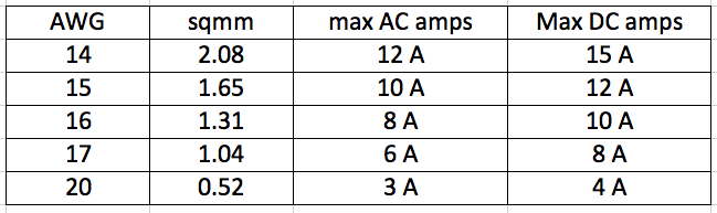
It’s OK if the current surges way above this value in a gust, but this is the maximum sustained current I would design for, as a safe target. Your furling tail should prevent the machine from kicking out more than this on a continuous basis. If output is higher then make the tail lighter to reduce amps.

Hi Hugh,
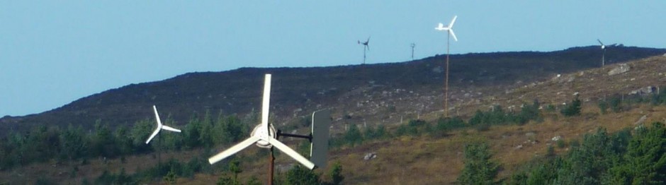
I am designing a AFPMG for a VAWT, the rpm of the turbine is normally 60RPM, I would like derive 1KW power @ 48V to charge a battery bank of 48VDC, I have used double rotor of 20+20 N52 magnets, there are 15coils and connected in 3 phase wye layout, I am not able to decide the coil wire diameter and number of turns, could you please guide me on this.
hi David,
I would not recommend using one of my axial flux alternators. they are designed to work at low rpm and the main priority is to offer best efficiency at part load (in low winds, when power is precious) and they do not perform so well at full power (in high winds when there is plenty of power).
Actually 2000 rpm constant is ideal for a conventional style generator, so I suggest using a capacitor excited induction motor or suchlike for this application. This will cost much less, be robust and should perform better at this high speed.
cheers
Hugh
Hello Hugh
I am doing experiments on energy capture and my latest requirement is to convert an anticipated power of between 3 & 4kW into electrical power. The power source is constant, and fixed (so no yaw) and operates at an anticipated 2500 to 2000 rpm. Can you give me an idea of sensible diameters of rotor and stator and coil/magnet arrangement that would likely fit the bill? There is no constraint of output voltage, it can be whatever it turns out to be. The system should be as efficient as reasonable achievable. Also I would be interested to receive guidance on how I might reduce the torque requirement of the pmg by control of the air gap in case I discover that it is overloading the drive. Is there a tested practical arrangement I might make use of?
I keep returning to your excellent book ‘Windpower Workshop’ which has inspired me over the years.
Many thanks
David Rees