Back in the 1980s I had spent ten years building wind turbines that were based on dynamos (USA=’generators’) out of military jeeps. They were cheap and well made, but they had serious drawbacks. The magnetism required to make them work took the first 40 watts or so of the power generated, and consumed it within the field coils as a parasitic loss. They also has brushes that required periodic cleaning or renewal. The standard Scoraig windmill of the day had approximately 1.7 metre diameter 2-bladed high speed ‘propeller’ on an Austin Champ Jeep dynamo modified to produce 12 volts at around 500 rpm cut-in speed. Given a 10 mph wind you had enough speed and enough power to start working, but low winds meant using the old oil lamps. In a good stiff breeze you got 300 watts.
I was hankering for something more like the Bergey and Marlec turbines I had seen that used permanent magnet alternators with neither of the above problems. I was especially interested in the axial ‘air gap’ design that Marlec had adopted (originally designed by Faraday and used by several others). Marlec use 2 mechanical configurations, shown here in an illustration from my book ‘Windpower Workshop’.

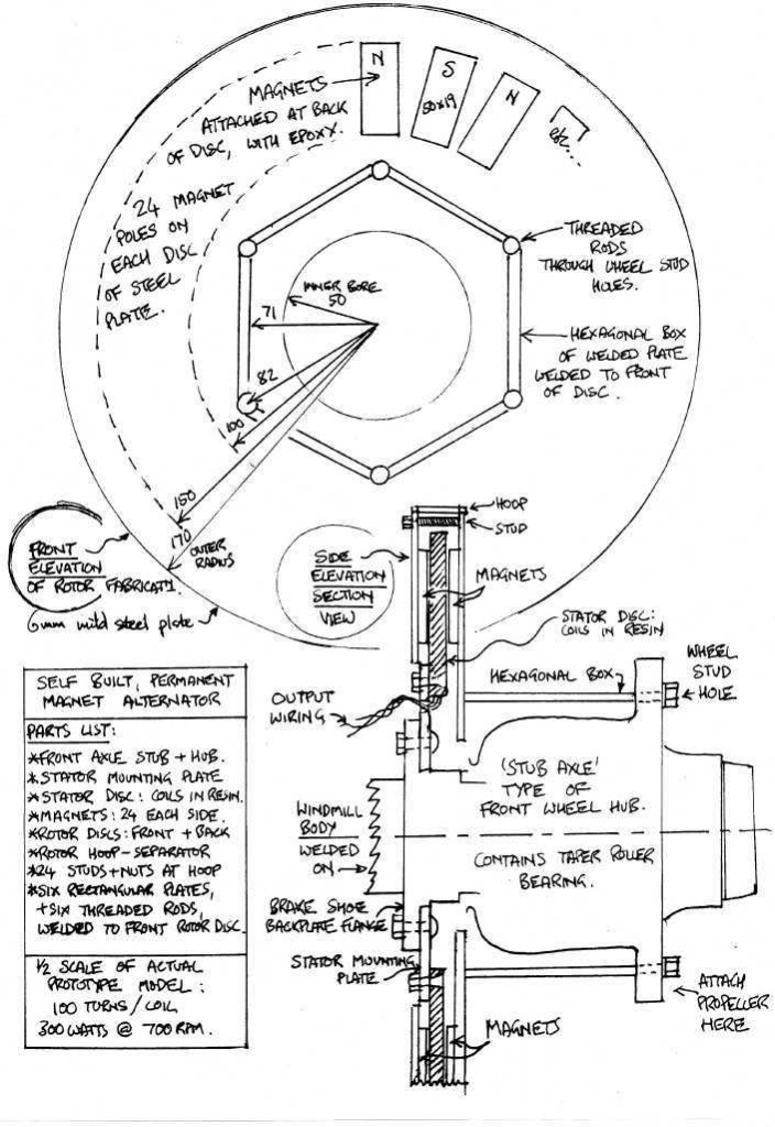
I built and tested my own axial flux alternator in about 1989, and I wrote it up (as a bit of a footnote) in my windmill plans of the day, a booklet called ‘Scrapyard Windpower Realities’. At the time Marlec were using single phase stators but I chose to go 3-phase and figured out a way of doing this whilst achieving a fairly high density of copper windings in the available air gap space between the magnet rotors.
This was in the days when I could still write with a pen. Now I am so used to typing that I can only scrawl.
I used a combination of delta and star connections in the winding. The star (wye) connected coils gave improved cut-in (300 rpm, which seemed good in those days) whereas the delta were more efficient at higher speeds. The idea was to create a sort of cubic curve (power/speed) that would better match the blades.
It worked pretty adequately for several years. In the end the magnets hit the coils for some reason – maybe because they were held in place only by epoxy glue or maybe the stator fell apart due to cracks caused by casting it with pure resin (no powder).
Maximum power was around 300 watts at 700 rpm. Overall I was disappointed. Magnets were expensive in those days, and the ones I used were rather thin (6mm) ferrites so the flux was poor. The construction seemed to me excessively complicated and the performance a bit weak. It did allow me to use a 3-bladed rotor though, and I gained control over the power/speed characteristics of the machine in a way that had never been possible with modified vehicle alternators and dynamos.
After that I played around with radial flux machines (notably the brake drum design, and the AWP) for about ten years, only returning to the axial style alternator in 1998. In February 2001 I published another axial flux design in my PMG construction manual that is available free of charge. It’s by no means the ultimate axial flux design – more like the start of a process of refinement. And most of the later versions have used neodymium (NdFeB) magnets. But the axial flux alternators with ferrite (aka ceramic) magnets that I built around that time have proved to be pretty efficient and reliable.


