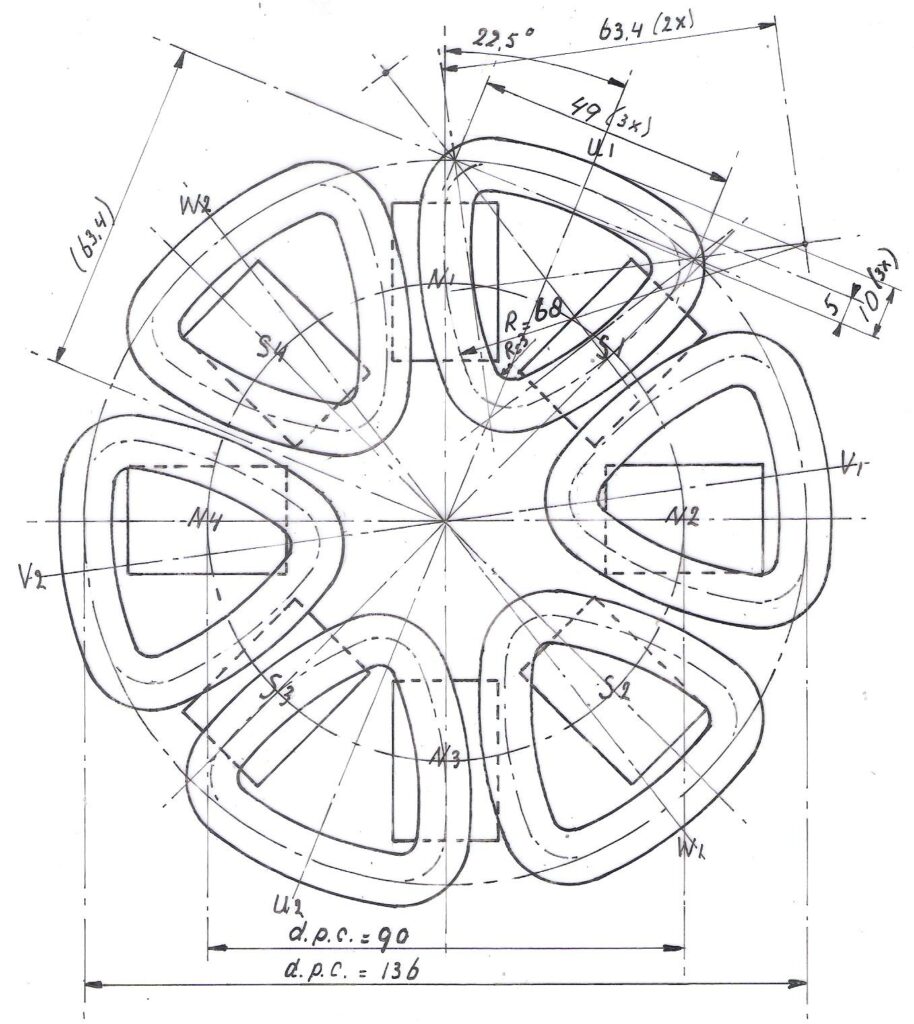
“Dear Hugh I have added a new chapter 9 in my public report KD 341 which may interest you. The title of this chapter 9 is: “Voltage generation in a coil”. This chapter also contains three pictures of a small 8-pole axial flux PM-generator which show how you go from the ideal coil shape to a shape which is easier to manufacture and contains more copper. KD 341 can be copied for free from my website: www.kdwindturbines.nl at the menu KD-reports. Adriaan Kragten”
It’s comforting to see that the coil shape arrived (below) at is similar to the ones I use in the F- series alternator designs, where I pack in the maximum number of ferrite magnets into the disk. With my Recipe designs for NdFeB magnets I used larger disks relatively and therefore a different coil shape.
My most recent wind turbine plans are dated 2014, and I don’t really make enough sales to justify updating them now but the list of UK suppliers at the back of my Recipe Book is out of date for sure. Often the best supplier will be a local one, but I will offer a list of suppliers below in case this is useful.
Magnets
Neodymium Blocks 46mm x 30mm x 10mm thick from Spider Magnetics These are grade N35 which is not particularly strong, but it is hard to find this size neo magnet these days. Powermagnetstore have N40 which is better for keeping the rpm down, but the cost is somewhat higher. You can get N42 from First4magnets but the cost is almost double the cost of the N35 ones. Thanks to Adriaan for pointing out Enesmagnets in Poland who can offer 50 x 25 x 12 magnets in N38 which should work well with the Recipes.
Find a local workshop that offers profile cutting services. Bear in mind that it will be much cheaper to buy a larger batch if possible (shared with friends?). I like to get them sent to be galvanized on their way to me. Another option is to get them powder coated but I don’t find this lasts so long in my maritime environment. It is possible to cut your own disks using a grinder (a big polygon works OK). Harder to get a precise result this way.
Trailer hubs
There are several online suppliers. Trailertek offer stub axles and hubs for small turbines around 2m diameter (beware of the seal behind the bearings which will not last due to thrust of the wind, so safer to remove this seal) and also some nice solutions for bigger machines at low cost. I have also used AutoW for hubs and they offer cheap options. Towsure are a good option too. You may wish to replace the bearings with decent ones such as SKF or other major brands.
I hope this helps. If anyone needs further advice please contact me at [email protected]
My wind turbine designs in recent years have used ferrite magnets and the naming system is based on “F” for ferrite (or ceramic) magnets, preceded by number denoting the diameter in metres. Hence the 2F is my 2012 design ferrite using ferrite magnets with 2 metre blade diameter and it is the only one that is available as a finished document for sale as hard copy or ebook. I have also built 3F, 4F and several 3.6F machines and I have a designs for a 1.2, 2.4 and 5F. Details of these models are available to people who contact me and ask for them in person.
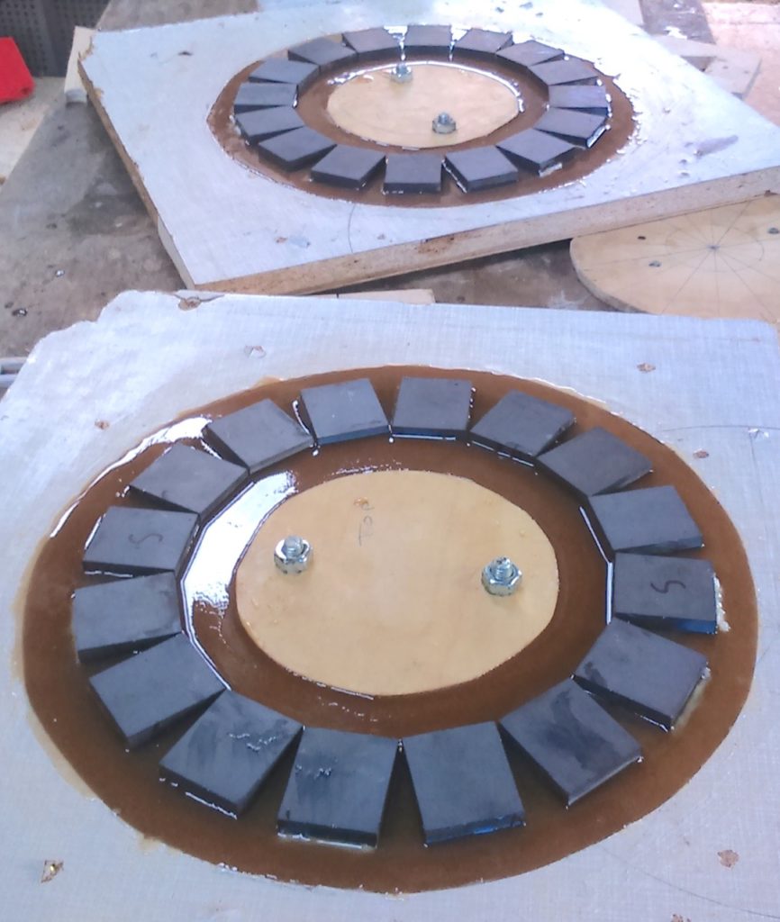
16 pole version of the 2F – magnet rotors in the moulds
I first started building ferrite magnet machines around 1991. I produced designs for various geometries including the radial flux “Brakedrum windmill plans” and African Wind Power 3.6m turbine in Zimbabwe (AWP), and the axial flux design for ITDG/Practical Action machines in Sri Lank and Peru around 1999-2000.
Here is a detailed design document for this generation of axial flux design. In those days these magnets were expensive. This illustration below (from 2001) shows the layout with the magnets quite widely spaced. The logic was that they were costly and this layout gave me the best best “bang for my (magnet) buck”. These magnet rotors have proved extremely reliable but the power output is low, around 100-200W maximum. Good long term energy producers though.
In 2001 I got my first taste of NdFeB magnets or “neos” at a Workshop in the USA. The magnets were provided by Otherpower and they were very strong and very shiny. For the next ten years my designs were all based on these sexy new magnets. This culminated (2009) in the Recipe Book series of designs that have become very popular worldwide, leading to the creation of the Windempowerment network. Unlike the older ferrite designs they had much higher power/weight ratio, made possible by the very powerful neo magnets.
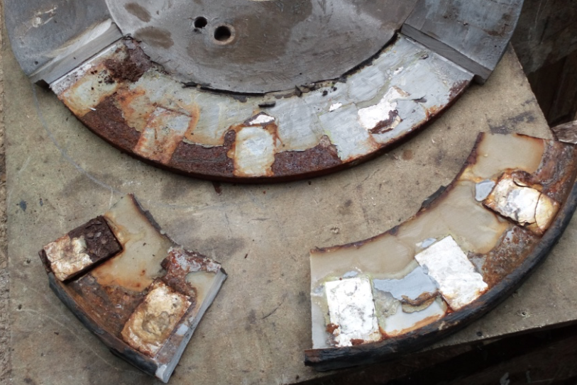
Corrosion issues in NdFeB magnets on Scoraig – The casting has been cut open for repair.
There are many machines built using these magnets, and they work well, but one persistent issue here on Scoraig (with our maritime climate) has been corrosion of the magnets. Inside their shiny coating they are extremely vulnerable to corrosion, which causes them to swell up. The resin casting fails to protect against this. When the corrosion starts at the back of the magnet (as in the above photo) the whole casting swells up and rubs on the stator. Some or all of the magnets eventually need to be replaced. Upgrading to galvanised disks helped a bit. Sometimes the issue can be dealt with for a few years using oil and grease to protect the magnets, but eventually there is a costly repair. It’s disappointing, and it has turned me back to using ferrite magnets that are immune to any kind of corrosion.
By 2012 the cost of ferrite magnets had fallen dramatically compared to the turn of the century. This enabled me to use a new approach of “throwing magnets” at the problem and so to maximise the flux in the air gap I crowded the rotor with big thick magnets, trying to fill the space. This is the opposite to my previous philosophy of trying to get the most power from the magnets I had (spaced sparsely on a large disk). Nowadays I try to get as many magnets onto the disk as I can. The optimum coil shape has also consequently changed from square with a large hole, to triangular with a small hole in the middle.
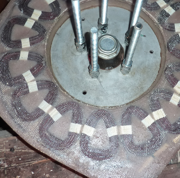
4F coils in the stator
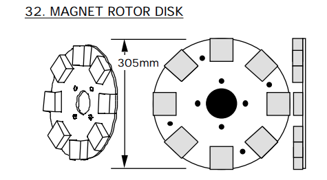
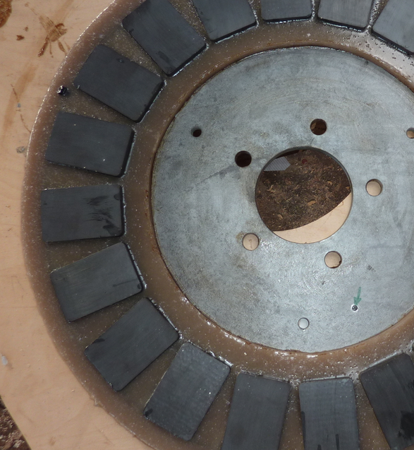
4F magnet rotor
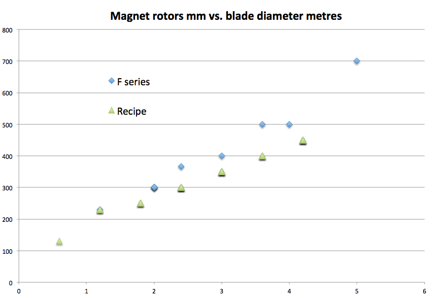
The result of this new approach is that the performance of this new generation of ferrite alternators is much closer to the equivalent sized neo alternator than one would expect, given the much less powerful magnet type. This chart compares the magnet rotor diameters. The F series are slightly larger but they produce roughly the same power output at the same rpm as the NdFeB magnet equivalents. (The 3.6F is a bit higher power than the neo one.)
The long awaited final version of Jon’s study based on data he collected here in 2012-2014 has finally been published and is free to read or download here courtesy of Wind Engineering.
An important conclusion is the the table in the Recipe Book that shows the anticipated energy yields for various site windspeeds was (amazingly) not too grossly misleading. “Piggott’s estimates for the annual energy yields of his Recipe Book machines are an accurate prediction of their average real-world performance (+5/−20%). However, the performance of individual machines can be significantly above or below this (+70/−51%). These deviations are sometimes intentional, where reliability is prioritised over power performance, but often unintentional.”
Jon had already given me the basic data, much of which has been available on a page on this blog since 2015. The page complements his article in many ways, giving some more detail of the individual turbines’ performance.
I have been thinking a bit about how best to orient solar arrays lately. I know that the optimum angle (for maximum total energy generation per year) is quite low, because most of the energy arrives in the summer, but if you want to get consistent power year round then a steeper angle is desirable, to maximise the slender solar in winter. There are also issues around shedding snow in some places (steeper is better) and around making best use of bright diffuse cloudy light (lower angle is better for places that do not see much sun at all).
I had read that it makes sense to split the array and put one part facing east and another facing west (some buildings force you to do this) and in the end you can get almost as much energy per day that way, losing maybe 15% compared with a south-facing array. The east array works well in the morning and the west works well in the evening and so you get more consistent power output without the high peak in the middle of the day, which is likely to be more than your battery can actually absorb in some cases.
So that started me thinking about lead acid batteries and how you charge them and I realised that they take a lot of charge at first, but later in the day they need less because they have arrived at the absorption voltage and the current tapers downward during the absorption phase. During this downward taper, the charge controller is rejecting much of the solar power so it is effectively irrelevant whether your array can produce high power output (unless you have a diversion load such as water heating off the surplus solar which everyone should have but very few actually seem to bother with).
So the logic took me to a conclusion that I have not heard or seen before surprisingly and I thought I’d share it here. If you face your array south east then you can get about 50% higher power in the morning, thus getting the battery charged quicker. Having reached the absorption voltage in the middle of the day, the array needs less power in the afternoon so it does not matter that this is less than you could have had available using a south facing array.
Here are some charts of solar power availability hour-by-hour to 2 arrays sited where I live, one facing south and the other south east (each at 45 degree angle) showing how the available power varies over the hours of the day in each month of the year. I got this data from https://re.jrc.ec.europa.eu/pvg_tools/en/tools.html The red curve is south facing and the blue one is the south east facing array.
It may not look like it, but the blue curve is about 50% higher power than the red one in the mornings which I reckon will bring the battery up to its absorption voltage quicker and allow it to absorb more power in the course of a day than it could with the red curve, even though the red curve offers more energy overall. That’s because you can’t actually use that extra afternoon energy to charge a lead acid battery because it cannot absorb power at such a high rate during the latter part of the charging cycle.
PowerSpout plan to increase prices of their hydro turbines and associated gear by approximately 15% on 1st April. This will be the first rise in several years. At present exchange rates, a turbine costs approximately £1190 with an additional £150 shipping cost from NZ. Often you can add a few items to your order and get free shipping.
To accept an order we need some detailed site information. I can help you with this and with the details of your hydro system design and let you know if it’s going to be worth doing or not. I spend much of my life these days chatting with people on email or phone to sort these things out and it’s a fascinating task. So feel free to get in touch if you are interested and you have a site in mind.
You can also use the PowerSpout drop down menu above to access more info and reading matter.
Recently I have written two new reports about small PM-generators which make use of the housing of an asynchronous motor frame size 80 and four neodymium magnets size 80 * 20 * 10 mm. Report KD 681 describes an 8-pole PM-generator which needs a rather simple 8-pole, 2-layers winding. Report KD 683 describes a 4-pole PM-generator for which the standard 230/400 V winding can be used. Both reports are added to my website www.kdwindturbines.nl at the menu KD-reports and can be copied for free.
It would be nice if you add this message to your blog.
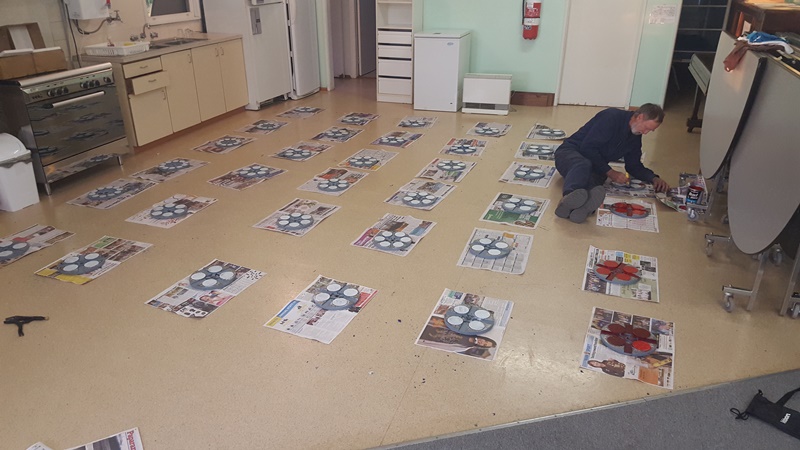
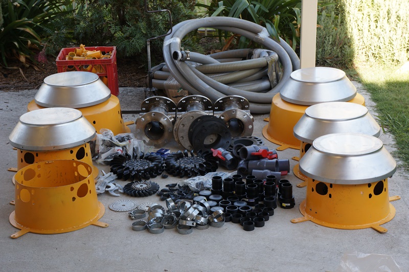
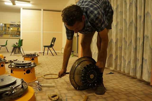
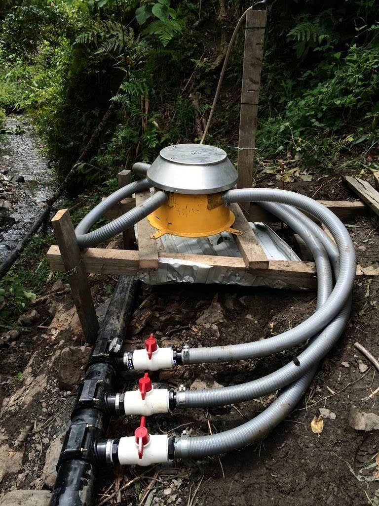
Greg sent me some photos of the hydros he is building using axial flux alternators to provide direct single-phase AC for sites in Papua, Indonesia. Here is some information. Greg’s email is [email protected]
These are single phase units, 240VAC, 50Hz.
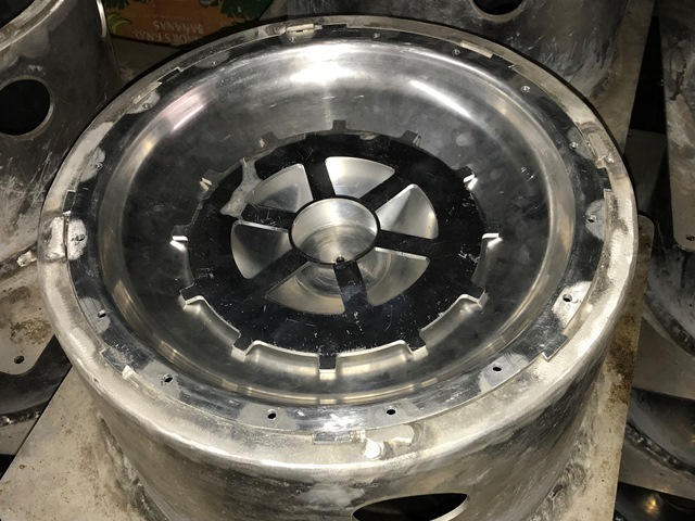
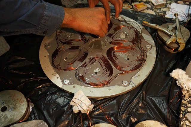
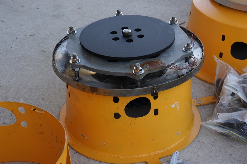
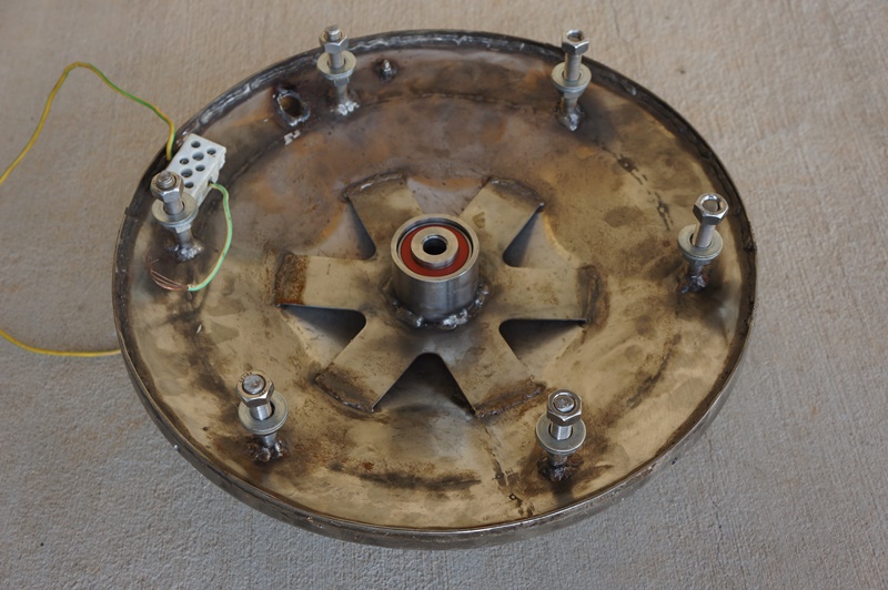
The first model (I made 6 units about 6 years ago) had magnets secured with a Stainless steel band and fibreglass epoxy. magnets are 60mm diameter. It is capable of up to 2.8kW (1000RPM). Measured efficiency was around 93%.
I started on 18 “Mark 2 machines” about 4 years ago, but life intervened and they have been on hold since. I’d be happy make a little report with a few more details if you think people would be interested.
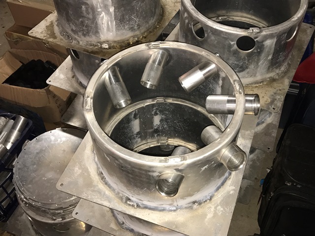
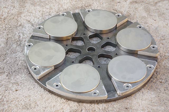
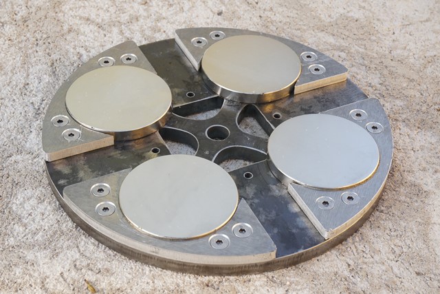
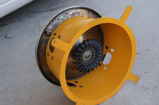
The second model is still under construction, but utilises aluminium magnet keepers for more positive magnet security and better cooling air flow. I also did a bit of coil shape optimisation (magnetic field computer simulation). I have a 6 pole (1000RPM) and 4 pole(1500RPM) version. I calculate that these machines will be capable of 4~6kW maximum, partly due to larger magnets and lower coil resistance, but mainly due to better cooling.
My Mark 1 machines had both pelton and turgo turbine options. I used an Eco-innovation plastic pelton wheel for the high head sites, and two sizes of turgo turbine for lower head sites. I bought the buckets from [email protected] in Italy. My Mark 2 machines will also use three different turbine diameters to accommodate different head sites, but they will be turgo turbines only. I am thinking to make my own turgo buckets, possibly by 3D printing…
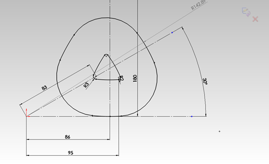
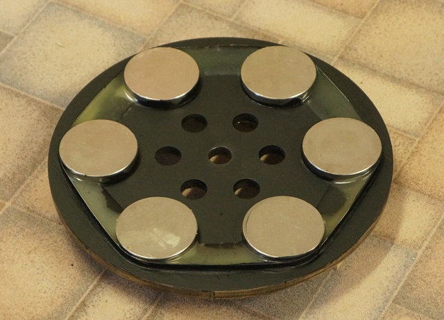
I went with circular magnets thinking they would give more sinusoidal voltage. Below is the design coil dimensions of my Mark 2, 6-pole generators. The magnets on this machine will be 70mm diameter running at a pitch circle of 88mm. According to the simulation, this gave the best compromise between high magnet flux capture and low copper volume with good sinusoidal waveform. I haven’t actually built one to test yet though.
The machines are regulated with an electronic load controller (dump load controller). The ELC I am using regulate frequency (eg 50Hz). Voltage seem fairly stable as long as frequency is well regulated. (I am working on my own ELC actually, due to shortcomings with some commercial ones we have tried)
Hope you get some joy out of seeing the work of a fellow renewable energy enthusiast!
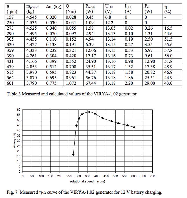
Adriaan Kragten has tested one of his small alternator designs and published results showing it is compatible with a 1.02m diameter rotor for a low power wind turbine.
A new chapter 6, “Generator measurements”, has been added to public report KD 678. A teacher of a technical school has built the 8-pole generator of the VIRYA-1.02 and I have measured this generator on my test rig for a 12 V battery load. The torque level of the generator appeared to be lower than expected but the matching in between rotor and generator is still acceptable. The maximum electrical power for the rated wind speed of 8 m/s is about 24 W.
Hi, I have my own Piggott wind turbine for 2 years, a 180cm 350W. I had some trouble about the way a regulator adapts energy to a battery charger or a injector. So I made my own regulator, which is a real MPPT for wind turbine and costs less than 50€. May be you will be interested, so here is the link :
There are many regulators on the market. However they are mostly adapted for solar panels only, and if the curve of delivered power is similar, the way to regulate is different – to resume solar panels use buck converter, wind turbines use boost converter. Many are not MPPT, the PWM regulators are very less efficient than MPPT, and also specific wind turbine MPPT regulators are very expensive.
So, It can be a very good project to self-build our own regulator, after having been built our own Piggott wind Turbine
From: Mike Allen
Subject: Re: A Wind Turbine Recipe Book
Date: 12 April 2013 10:53:18 BST
To: jytte
I recieved the book yesterday and when it arrived I thought ‘this isn’t worth £12’.
But how wrong I was once I’d opened the envelope and settled down to read the contents with a cup of coffee. 3 hours later the coffee was stone cold and I was still reading the book.
Loads of info to be getting on with.
I’ll email Hugh when my terbine is up and running with some pics.